language
 русский
 عربى
 Indonesia
Home / Blog / Industry News / Pump Head and Flow Rate Explained: How to Read a Pump Curve and Duty Point
News


 2026.11.19
 Industry News
A pump curve answers one question in a single line: at this flow rate, the machine will deliver this much head. Everything else printed on the sheet — efficiency, shaft power, NPSH required, minimum continuous flow — is a qualification of that one line. Read the line correctly and the selection holds together on site. Read it loosely and the pump ends up running somewhere other than where the drawing said it would.
Three conditions are frozen into every published curve before you read a single number. The curve is drawn at one fixed shaft speed, normally 1450 rpm or 2900 rpm on a 50 Hz supply. It is drawn for clean water near 20 °C at a specific gravity of 1.0. And it is drawn for one specific impeller diameter, not for every trim the casting can accept. Change the speed with a variable frequency drive, change the impeller, or pump a liquid at 1.25 specific gravity, and the printed sheet is no longer the curve the pump will follow.
Units catch more buyers than hydraulics do. A duty of 45 m equals about 4.4 bar. When a sheet published in bar is compared against a system calculated in metres and somebody reads the 4.4 as 4.4 m, the pump ordered is roughly ten times too small. On international projects where supplier and buyer work in different conventions, that conversion deserves a second pair of eyes before the purchase order is signed.
Flow runs along the horizontal axis — cubic metres per hour, litres per second or US gallons per minute. Total head runs up the vertical axis in metres, feet, bar or kPa. Drop a vertical line at the flow you need and the point where it meets the head curve tells you what the pump can produce there. Run a horizontal line at the head your system demands and the point where it meets the curve tells you how much flow will pass.
That single exchange is the whole logic of the sheet. The curve slopes downward to the right because a centrifugal impeller can only convert a fixed amount of rotational energy into pressure. Send more liquid through the same impeller and each kilogram of it leaves with less energy, so head falls. At zero flow the pump produces its maximum head, called shut-off head, and at the far right of the curve the head has fallen so far that the pump is doing very little useful work.
The vertical axis is measured in metres but does not mean the pump lifts water that many metres. Head is the energy the impeller adds to each unit weight of liquid, expressed as the equivalent height of a liquid column. A pump rated at 40 m can raise water 40 m through a frictionless vertical pipe, or push it 400 m horizontally through a pipe with enough wall friction to absorb the same energy, or discharge it into a vessel held at 3.9 bar — or do a combination of all three that adds up to 40 m.
This is why comparing the raw numbers on two quotations tells you almost nothing. A pump quoted at 32 m against a system needing 25 m of lift plus 11 m of friction is short by 4 m, even though 32 looks bigger than 25. A pump quoted at 55 m against a system needing only 30 m will be throttled back by a partly closed valve for the rest of its service life, and the energy burned across that valve is never shown on any quotation.
Total head on the discharge side of any installation is the sum of four terms. Written out in the form used for pump selection:
H = (p₂ − p₁) / (ρg) + (v₂² − v₁²) / 2g + (z₂ − z₁) + Hf
The first term is pressure head, the difference between the pressure at the discharge point and the pressure at the suction source, divided by the density and gravity. The second is velocity head, the difference in kinetic energy between the two flanges. The third is static lift, the vertical distance between the liquid surface on the suction side and the liquid surface or discharge point on the other side. The fourth is friction and fitting loss through the pipework. Only the first and third are visible on a site walk-round; the other two are calculated, and both are routinely underestimated.
Static liftMeasured between liquid surfaces, not pipe centrelines. A tank with 2 m of water in it has its surface 2 m higher than the empty tank floor, and that difference changes the duty.
Pressure headZero in most open discharge arrangements, but significant in closed loops, spray systems, boiler feed and any discharge into a pressurised vessel.
Friction lossScales with the square of flow. Doubling the flow quadruples the friction term, which is why a system curve bends upward so sharply on the right.
Velocity headSmall in most installations but not negligible when the discharge nozzle is much smaller than the suction pipe. Ignoring it costs a metre or two of margin.
| Component | Symbol | How to capture it on site | Common error |
|---|---|---|---|
| Static lift | z₂ − z₁ | Level gauge or tape on both liquid surfaces | Using pipe centreline heights instead of actual liquid levels |
| Pressure head | (p₂ − p₁)/ρg | Pressure gauge at the discharge flange | Assuming an open tank when the line discharges below the liquid surface |
| Friction and fittings | Hf | Darcy–Weisbach or Hazen–Williams plus fitting K values | Using nominal bore for aged steel pipe whose internal diameter has narrowed |
| Velocity head | (v₂² − v₁²)/2g | Flow divided by internal flow area at each flange | Applying suction velocity when the inlet draws from a large slow-moving tank |
Friction deserves its own note because it decides the shape of the system curve. The Darcy–Weisbach form gives Hf = f · (L/D) · (v²/2g) for straight pipe, plus a sum of K · (v²/2g) terms for bends, valves, strainers and sudden contractions. A single globe valve can carry a K value of 6 to 10; a fully open gate valve carries about 0.2. When a buyer reports that a new pump "cannot reach the tank", the difference between a globe valve and a gate valve is often the whole explanation.
The order matters. Reading head first and NPSH last is how cavitation damage gets ordered on a machine that looked perfectly sized on paper.
The highest point of the efficiency curve is the best efficiency point, and it is a property of the hydraulic design rather than of your installation. The duty point you selected is where the system curve happens to cross the pump curve, and nothing guarantees the two coincide. Hydraulic institute guidance puts the acceptable continuous operating band at roughly 70 % to 120 % of best efficiency flow. Run below that band and recirculation inside the casing starts to erode the impeller and heat the liquid; run above it and the shaft deflection, radial loads and NPSH requirement all climb together.
| Reading | Value at 111 m³/h | What it decides |
|---|---|---|
| Head produced | 35.8 m | Whether the system curve is met without throttling |
| Efficiency | 76 % | Running cost and heat input to the liquid |
| Shaft power | 14.3 kW | Motor rating, with a service factor applied to the curve maximum |
| NPSH required | 3.4 m | Suction lift limit and tank elevation |
| Minimum continuous flow | 33 m³/h | Whether the pump can be allowed to run at low demand |
| Shut-off head | 47 m | Pressure rating of downstream pipework and valves |
The shaft power figure is worth checking by hand, because a curve printed with a wide power band can hide a motor selection error. Hydraulic power is ρgQH, and shaft power is that divided by efficiency. With water at 1000 kg/m³, 111 m³/h converts to 0.0308 m³/s; multiplying by 9.81 and by 35.8 m gives 10.8 kW of hydraulic power, and dividing by 0.76 gives 14.3 kW at the coupling. A 15 kW motor running at 100 % of its rating on a continuous duty is a motor with no margin. An 18.5 kW frame is the sensible choice.
A pump never decides its own operating point. The system decides it. Plot the head the installation demands at every flow and you get the system curve, which follows the form H = Hstatic + kQ². The static part is fixed by the elevation difference and any pressure held at the discharge. The kQ² part is friction, and it grows with the square of flow.
The point where the two curves cross is the only point at which the pump will actually run. Everything else on the sheet describes behaviour at flows the installation will never ask for.
Take the worked case in the chart. The static head is 16 m, and at 120 m³/h the friction in the pipework adds 23 m, giving a k value of 23 divided by 14 400, or 0.0016. Solving the intersection of both curves puts the duty point at 111 m³/h and 35.8 m. Notice what the chart shows about the right-hand side of the operating range: an extra 20 m³/h of demand costs almost 6 m of head, because friction is eating the pump's output faster than the impeller can produce it.
Efficiency, power and NPSH are plotted against the same horizontal flow axis, which makes them easy to read together and easy to misread if only one is checked. Efficiency peaks somewhere near the middle of the curve and falls away on both sides. Shaft power either rises steadily with flow, flattens, or falls, depending on the specific speed of the impeller — a low specific speed pump drawing 12 kW at shut-off may draw 20 kW at full flow, while some mixed flow designs behave in the opposite way.
Order a pump for 111 m³/h and the natural instinct is to size the motor at the power read from that point. That instinct fails whenever the actual system curves flatter than expected. If a valve is left open and the pump runs out to 180 m³/h, the power curve — not the duty point — decides whether the motor trips. Read the maximum shaft power anywhere on the usable portion of the curve and add a margin of 10 % to 15 %. Where the curve is expected to shift, a 15 kW motor on a 14.3 kW duty is common practice and an 18.5 kW motor is safer.
NPSH required is the net positive suction head the pump needs at its impeller eye to keep the lowest pressure point in the casing above the vapour pressure of the liquid. NPSH available is what the installation provides:
NPSHa = (patm − pv) / (ρg) + zsuction − Hf,suction
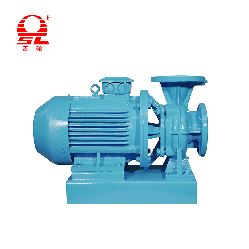
In practice the theoretical 10.33 m of atmospheric head at sea level never materialises. Water at 20 °C has a vapour pressure of 0.23 m, the suction pipe and fittings consume 1 to 2 m, and a real installation that pulls water from a sump 6 m below the pump centreline is already close to the limit for a standard end-suction design. Self-priming pumps buy themselves a little more tolerance by holding a liquid reservoir in the casing during priming, but the NPSH limit still applies once priming is complete.
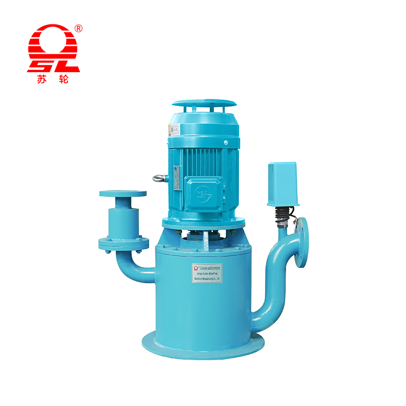
The WFB series non-sealed self-priming pump we build in volume illustrates the point: its NPSH requirement climbs quickly beyond about 70 % of rated flow, and a duty chosen on the far right of the curve that looks efficient at first glance will cavitate once suction friction rises in service.
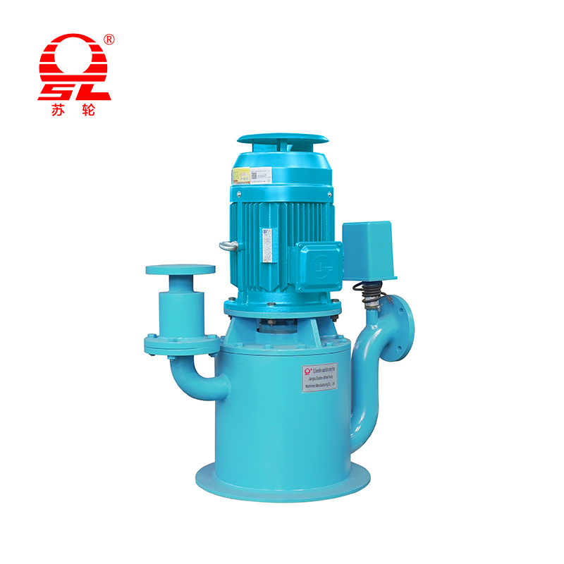 WFB Seal-Free Self-Priming Pump SeriesSelf-priming to 7 m with seal-free design, suitable for slurries and chemicals, but NPSH demand rises at high flow, so curve selection matters.View Product →
Keep at least 0.5 m of margin between available and required NPSH, and 1.0 m where the liquid is hot, the suction line is long, or the pump will run at part load for long periods. Temperature is the variable that catches people out: raising water from 20 °C to 80 °C cuts the available head by roughly 4 m because vapour pressure rises sharply, and a curve that was comfortable in winter becomes marginal in summer.
The affinity laws let you predict a whole new curve without asking the manufacturer for another drawing. They hold well for geometrically similar impellers and small changes of speed, with accuracy that degrades as the change gets larger.
| Parameter | Relationship | Factor at 0.828 speed | New value |
|---|---|---|---|
| Flow rate | Q ∝ n | 0.828 | 92 m³/h |
| Head | H ∝ n² | 0.685 | 24.5 m |
| Shaft power | P ∝ n³ | 0.567 | 8.1 kW |
The third row is why variable speed drives pay for themselves so quickly on any system with a throttling valve. A 17 % speed reduction cuts power by 43 %, and the energy that used to be dissipated across a partly closed valve simply never enters the water. On a 24-hour drainage station or a cooling circuit running all year, that difference usually returns the cost of the drive inside two years.
Reducing impeller diameter reduces flow roughly in proportion to diameter and head roughly with the square, but the relationship is only reliable for trims of about 10 % to 15 %. Beyond that the volute and the casing cutwater no longer match the reduced impeller, efficiency drops faster than the law predicts, and the best efficiency point shifts left. A model supplied with a full-diameter impeller and then trimmed on site is a legitimate way to fine-tune a duty, but it is not a substitute for selecting the right casing in the first place.
The four head components do not change when the liquid changes, but the power does. A pump handling a liquid at 1.25 specific gravity produces exactly the same head and flow at the same speed — and consumes 25 % more shaft power. That is the single most common motor-size error on chemical and slurry duties: the hydraulic selection is correct and the motor frame is undersized.
Viscosity behaves differently. Above roughly 100 cSt, friction inside the impeller passages starts to matter and the pump's own performance changes: flow falls, head falls, efficiency falls and power at the duty point may rise. The corrections published in the hydraulic institute standards are the usual reference for this, and applying them before selection is far cheaper than discovering the shortfall after commissioning.
Solids content adds a third effect. A slurry with 20 % solids by weight behaves as a denser liquid for power purposes and as an abrasive fluid for wear purposes. Open or semi-open impellers pass larger particles than closed designs but give up efficiency. Hardness of the particles matters more than their concentration: sharp silica sand at 5 % will wear a standard cast iron impeller faster than rounded clay solids at 15 %.
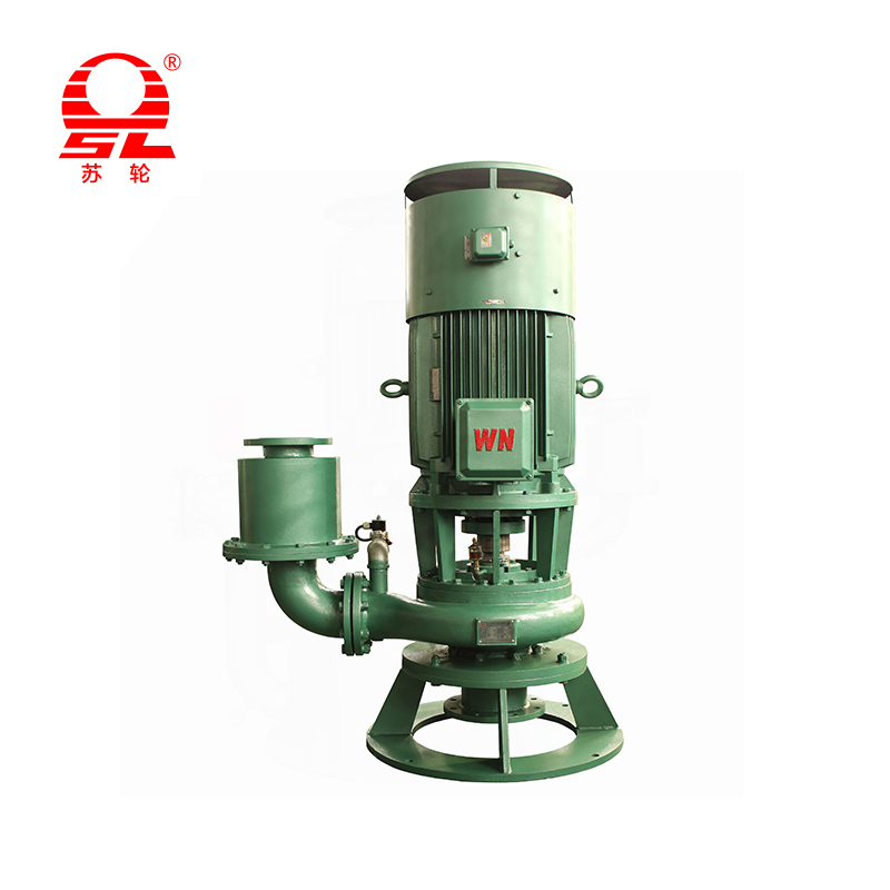
For sump and sewage duties the curve also has to survive the real fluid. Rag, grit and fibrous material change the effective viscosity at the impeller and can reduce head by several metres within weeks of commissioning if the impeller passage is too tight. A vertical multi-suction sewage pump handles this by drawing from several levels, which keeps the approach velocity low and reduces the chance of a solids mat forming at the suction bell.
 SLPWDL Multi-Suction Vertical Sewage PumpMulti-suction inlet and large-channel impeller reduce clogging and cavitation when handling slurries with solids and fibers in industrial sewage duties.View Product →
Most disagreements between a pump supplier and a plant operator trace back to one of a small number of reading errors. None of them are exotic.
| Reading error | What happens on site | Correction |
|---|---|---|
| Duty point taken at rated flow without a system curve | Pump runs to the right of the intended point, motor overloads or NPSH margin disappears | Plot the system curve before ordering, including the low-flow and high-flow ends |
| Motor sized on duty-point power only | Tripping during commissioning when valves are fully open | Size on maximum power anywhere on the usable curve, plus 10 % to 15 % |
| Water curve applied to a slurry | Motor overload of 20 % to 30 %, rapid impeller wear | Apply specific gravity correction to power and wear allowance to materials |
| NPSH checked at design flow only | Cavitation and pitting when the pump runs above design flow | Check NPSH required across the whole operating range, especially the right-hand end |
| Curve read at 60 Hz but pump supplied at 50 Hz | Flow and head roughly 17 % below expectation | Confirm the speed printed on the curve matches the motor and supply frequency |
| Friction calculated for nominal bore rather than actual bore | Flow falls short by 5 % to 15 %, blamed on the pump | Use internal diameter, and allow for scaling in old steel lines |
Two of these deserve a closer look. The 50 Hz and 60 Hz confusion is almost entirely an export-order problem, and it appears when a buyer receives a curve generated for a 60 Hz market and installs the pump on a 50 Hz supply. Flow and head do not simply stay the same; they follow the affinity laws, which means a nominal duty of 120 m³/h at 40 m becomes roughly 100 m³/h at 28 m. On a system with 30 m of static lift, that pump will not deliver any water at all.
The second is the low-flow mistake. A pump selected near the middle of its curve and then operated at 30 % of that flow for long shifts is running in the recirculation zone, where the liquid inside the casing is being churned rather than discharged. Temperature rises, vibration rises, and the impeller erodes at the suction eye. A minimum-flow bypass or a level-control strategy that keeps the pump inside its band is cheaper than a replacement impeller every 18 months.
The gradient of the head curve is as informative as any single number on it. A steeply falling curve means a small change in flow produces a large change in head; a flat curve means the opposite. Each shape suits a different kind of installation.
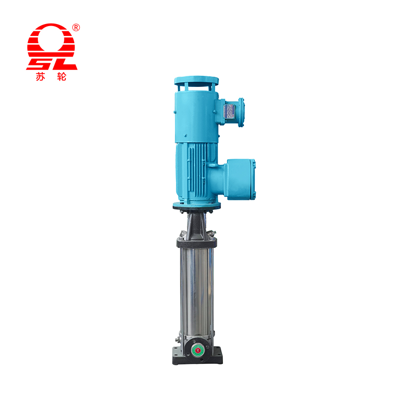
Long shaft pumps illustrate the point in a different way. Their curves are often flatter than a comparable end-suction pump because the long column adds friction that varies with flow, flattening the net head available at the discharge. That is one reason the selection process for deep sump and wet-pit installations has to include the column and discharge pipework in the system calculation, not treat them as part of the pump. The principles are covered in our introduction to long shaft pump selection, and they apply whether the column is 3 m or 12 m long.
In a closed loop there is no static head at all, which changes the calculation completely. The system curve starts at zero and rises only with friction, so the operating point is decided entirely by pipe, coil and valve losses. A vertical pipeline centrifugal pump installed directly in the rising main is efficient in this role because it avoids the extra bends and elbows a horizontal machine would need, and every avoided fitting removes a K value from the friction sum. In these installations, checking the flat part of the curve matters more than checking shut-off head, because the pump never runs anywhere near shut-off.
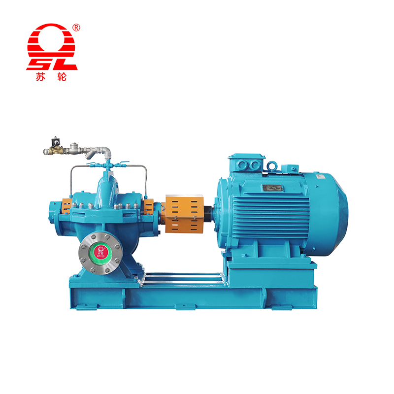
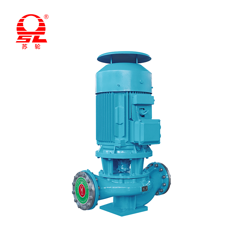 SLG Vertical Pipeline Centrifugal PumpCompact vertical pipeline design minimizes fittings in closed-loop systems, and full-size performance testing ensures the published curve matches actual head-flow behavior.View Product →
A curve is a promise made before the casting is machined. Our hydraulic test platform covers impellers from 32 mm to 1200 mm in diameter, motors from 1.1 kW to 1200 kW, and supply voltages from 380 V to 10 kV, which means a full-size performance test can be run on the same frame that will ship — not on a scaled model. Each test records head at a series of flows, and the measured points are compared with the published curve before the machine leaves the bay.
Field verification follows the same logic with simpler instruments. Fit a pressure gauge at the suction flange and another at the discharge flange, install a flow meter in the discharge line, and read the motor current. Head is then:
H = (pd − ps) / (ρg) + (vd² − vs²) / 2g + z
with z the vertical distance between gauge centrelines. Gauge accuracy of ±2.5 % on a 6 bar discharge reading translates to ±1.5 m of head, which is why a field measurement that disagrees with the curve by 2 m is usually a measurement problem rather than a pump problem. Compare the measured point with the curve only after the flow has stabilised, the liquid temperature has been recorded, and the drive frequency has been confirmed.
Three practical checks catch most disputes before they start. First, confirm that the flow meter is installed with the straight lengths its manufacturer requires; a meter two diameters downstream of an elbow reads low by several percent. Second, confirm the actual pump speed with a tachometer rather than assuming the motor nameplate speed. Third, record the specific gravity of the liquid actually being pumped, because a 5 % error in density produces a 5 % error in the calculated head and a much larger argument about whose number is right.
Pressure is a force per unit area at one point; head is the energy added per unit weight between two points. A pump producing 40 m of head will show a discharge gauge reading of about 3.9 bar if the suction side is at atmospheric pressure, but the gauge reading alone does not tell you the head unless the suction pressure and the liquid density are both known. Always convert gauge readings into head before comparing them with a curve.
Yes, up to a limit. At zero head the pump is running at maximum flow, sometimes called run-out, and the flow can exceed the right-hand end of the published curve by 20 % or more. Running there for any length of time overloads the motor, causes cavitation and puts excessive axial load on the bearings. Systems that can drain to zero head need a throttling device or a control valve that limits the maximum flow.
In order of frequency: the actual system head is higher than calculated, the pump speed is lower than assumed, air is entering the suction line, the impeller has worn, or the liquid is more viscous or denser than the design case. Measure the head at the flanges and compare it with the curve at the measured flow. If the measured point sits on the curve, the pump is fine and the system is the problem. If it sits below the curve, the pump is the problem.
For clean cold water and a steady duty, 0.5 m above the required value is the practical minimum. Use 1.0 m for hot liquids, long suction lines, part-load operation or any duty where flow may drift above design. In high-energy pumps and boiler feed applications, a margin expressed as a ratio rather than a fixed value is sometimes specified; follow the standard named in the project specification rather than a general rule.
It changes which curve applies. The shape of the head-flow relationship stays similar, but the whole curve moves down and to the left as speed falls, following the affinity laws. The system curve does not move at all, so the duty point slides along it. This is why variable speed control is so effective on friction-dominated systems and much less effective where static head dominates: with 25 m of static lift, a 20 % speed reduction may simply stop the pump from delivering any flow.
Only if the curve is read as a combined curve, built by adding the flows of both pumps at each head. Two pumps each rated 100 m³/h at 35 m will not deliver 200 m³/h at 35 m, because the higher combined flow raises the system friction and pushes the operating point up the curve. The combined flow is always less than double the single-pump flow, and the shortfall grows as the system curve steepens.
Six pieces of information are enough to check any duty against a published curve and come back with a firm answer rather than an estimate.
With those six items, the head can be calculated, the system curve plotted, and the intersection with the pump curve identified before a quotation is issued. That sequence is what turns a catalogue number into a pump that runs at the point the process actually needs.

+86-0523- 84351 090 /+86-180 0142 8659


Add 1: Hongguang Industrial Park, Jingjiang City, Jiangsu Province, China
Add 2: No.68, Xinyi Road, Industrial Park, Jingjiang City, Jiangsu Province, China
+86-0523- 84351 090
+86-180 0142 8659
+0523-8435 5588