language
 русский
 عربى
 Indonesia
Home / Blog / Industry News / What Is NPSH? How to Avoid Pump Cavitation in Reliable Industrial Pump Systems
News


 2026.11.16
 Industry News
A pump cavitates when the absolute pressure at the impeller eye drops to the liquid vapor pressure, vapor bubbles form, and then collapse as pressure recovers inside the casing. The practical answer is not a single NPSH number. The installation is safe only when NPSH available stays above NPSH required with a margin that still holds at maximum flow, maximum temperature, and the dirtiest suction strainer the system is likely to see. For most industrial pump selections, that margin should be at least 0.5 m to 1.0 m or 10% to 15% of NPSH required, whichever is greater. Hot, volatile, high-energy, and long-suction services often need more.
For Double-Wheel pump selections, NPSH required is checked on the duty curve at the specified flow, not only at the best efficiency point. The suction layout is reviewed with the same care as impeller hydraulic design because a pump that looks correct on paper can still fail in service if the suction system changes after commissioning.
NPSH stands for net positive suction head. It is the absolute pressure energy available at the pump suction, expressed in meters of liquid, after subtracting vapor pressure, static lift, and suction friction loss. NPSH available, usually written NPSHa, belongs to the system. NPSH required, written NPSHr, belongs to the pump. Cavitation risk is the relationship between the two, not the headline flow or head of the pump.
The common field formula is:
NPSHa = (p_atm - p_v) / (density x gravity) - H_static - H_friction
Use absolute pressure for p_atm and p_v. Use the actual pumping temperature, because vapor pressure rises sharply as liquid approaches its boiling point. Use the maximum suction lift, not the clean-condition lift. Include the pressure drop of the strainer, foot valve, inlet filter, elbow, and any long horizontal run before the pump flange.
| Term | Meaning | Unit and note |
|---|---|---|
| NPSHa | Absolute pressure energy above vapor pressure at the suction flange, after lift and friction losses. | Meters of liquid or kPa; calculated by the system designer. |
| NPSHr | Minimum NPSH at the impeller eye needed to limit head drop to the test basis, commonly 3%. | Meters at a stated flow and speed; read from the pump curve. |
| p_atm | Site atmospheric pressure at the pump centerline. | About 101.3 kPa at sea level; lower at altitude. |
| p_v | Liquid vapor pressure at pumping temperature. | kPa absolute; temperature dependent. |
| H_static | Static suction lift from liquid surface to pump centerline. | Meters; positive when the supply is below the pump. |
| H_friction | Suction friction loss including pipe, fittings, strainer, and valves. | Meters; rises with flow and fouling. |
| Margin | NPSHa minus NPSHr at the same flow and liquid condition. | Target at least 0.5 m to 1.0 m or 10% to 15% of NPSHr. |
A clean suction strainer can hide a marginal installation for weeks. As the strainer loads, friction loss increases, NPSHa falls, and the pump begins to sound as if gravel is passing through the casing. The same effect appears when a suction valve is throttled, a parallel pump is started, or a tank level drops below the design minimum. Temperature has an even stronger influence. Water at 20°C and water at 90°C can use the same pipe layout but behave very differently because vapor pressure is no longer a minor correction.
NPSHr also moves with flow. A pump selected at 70% of best efficiency point may have a comfortable NPSHr at that flow, but a later process change that pushes flow 15% higher can raise NPSHr while suction friction also increases. That double movement is why the NPSH review should be repeated at maximum expected flow, not only at the normal operating point.
A positive margin is not automatically a safe margin. The correct conclusion is that margin must match the consequences of interruption. A clean water transfer pump with a flooded suction and steady level can tolerate a modest margin. A boiler feed, condensate, chemical process, or high-temperature thermal oil pump cannot, because cavitation damage may occur before the operator notices a head loss. In those services, the design review should use the maximum temperature, minimum tank level, maximum flow, and blocked strainer condition.
Robust margin
NPSHa 7.1 m, NPSHr 2.8 m. Margin 4.3 m. Typical of a flooded clean-water installation with conservative suction piping. Normal monitoring is enough.
Tight margin
NPSHa 3.8 m, NPSHr 3.2 m. Margin 0.6 m. Common with hot condensate or a high suction lift. A strainer load or level drop can consume the margin.
Unacceptable margin
NPSHa 4.9 m, NPSHr 4.5 m. Margin 0.4 m. A long suction line with elbows and a foot valve can move this into cavitation during startup.
NPSH available versus required, three installation examples
Pump curves commonly define NPSHr at a 3% drop in developed head. That definition is useful for comparison, but it does not mean the pump is damage-free at 3.01% head drop. Vapor bubble collapse can remove material from the impeller eye, wear ring, and casing long before the curve shows a clear change. For abrasive slurries, chemical liquids, and high-energy impellers, the acceptable operating margin should be based on inspection experience and material resistance, not only the guaranteed test point.
Specific speed matters as well. High-energy, low-specific-speed impellers can show aggressive cavitation damage at the inlet while the performance curve remains close to normal. Lower-speed and double-suction designs spread the inlet flow over a larger area and often reduce NPSHr, but they still require a correct suction system.
Cavitation usually begins in ordinary places: a suction line with one extra elbow, a tank outlet too close to the surface, a strainer selected for a clean pressure drop rather than a dirty one, or a pump installed above a sump because the drawing had space there. The fault is rarely the impeller alone.
Long horizontal suction lines
High friction, air pockets, and a foot valve that does not seal can all reduce NPSHa. A line sized for 0.8 m/s may look generous, but an undersized strainer or partly closed valve can consume more head than the pipe.
Hot liquid service
Vapor pressure rises quickly with temperature. A pump that works with cold water may cavitate when the same tank is heated, even if the level and piping are unchanged.
Self-priming suction lifts
Self-priming pumps can handle suction lift, but the allowable lift is limited by NPSHa and priming time. Air leakage on the suction side and a worn mechanical seal can prevent stable priming.
Vertical long-shaft pumps
Deep sumps and pits require careful submergence and column design. Vortexing, entrained air, and a low liquid level can create cavitation even when the pump is physically submerged.
Chemical process transfer
Solvents and volatile chemicals may have high vapor pressure at ambient temperature. NPSHr must be checked with the actual liquid properties, not water curves.
Parallel pump operation
Starting a second pump can change the suction header pressure and increase flow through a shared strainer. The NPSH calculation should cover the worst combination of running pumps.
A useful field check is to compare the sound at the pump inlet with the sound at the discharge. Cavitation often produces a crackling or rattling noise near the casing, together with vibration and a slow loss of head. The symptom is not proof. Air entrainment, recirculation, and mechanical rubbing can sound similar, so pressure readings and flow checks are needed before the pump is opened.
The calculation is simple only when the inputs are honest. Use absolute pressure, the highest liquid temperature, the lowest liquid level, and the maximum flow. A suction strainer should be evaluated at its dirty pressure drop, not its clean pressure drop. For an existing installation, measure the suction vacuum and discharge pressure at the same time and convert the readings to meters of liquid.
Consider water at 60°C, a site near sea level, a static suction lift of 3.5 m, and suction friction of 1.2 m at the design flow. Atmospheric pressure is 101.3 kPa absolute. Vapor pressure is about 19.9 kPa absolute. Density is about 983 kg/m3. The pressure head above vapor pressure is (101.3 - 19.9) x 1000 / (983 x 9.81), which equals about 8.44 m. After subtracting 3.5 m static lift and 1.2 m friction, NPSHa is about 3.74 m.
| Input or result | Value | Comment |
|---|---|---|
| Atmospheric pressure | 101.3 kPa absolute | Sea-level site. |
| Vapor pressure at 60°C | 19.9 kPa absolute | Use actual temperature. |
| Density | 983 kg/m3 | Hot water, not 1000 kg/m3. |
| Static suction lift | 3.5 m | Minimum tank level. |
| Suction friction | 1.2 m | Dirty strainer included. |
| NPSHa | 3.74 m | At design flow. |
| NPSHr at duty | 3.20 m | From the tested curve. |
| Margin | 0.54 m | Too tight for a hot-water service. |
If flow rises by 20%, suction friction rises roughly with the square of flow. The 1.2 m friction becomes about 1.73 m, and NPSHa falls to about 3.21 m. The margin against a 3.20 m NPSHr is then only 0.01 m. That is the kind of change that turns a seemingly acceptable pump into a noisy, vibration-prone unit after a process adjustment. At higher elevation, the atmospheric pressure term also falls; a site at 1500 m may have only about 84 kPa atmospheric pressure, which removes more than 1.7 m of available head compared with sea level.
The most reliable way to avoid cavitation is to reduce NPSHr and increase NPSHa at the same time. Selection should start with the duty point and the suction system, not with a frame size that happens to be available. A larger suction pipe, a low-NPSHr impeller, and a slower speed can be more valuable than a higher-pressure pump that is forced to run near its suction limit.
| Design lever | Effect on NPSH | Practical caution |
|---|---|---|
| Increase suction pipe diameter | Reduces friction loss and raises NPSHa. | Avoid oversized horizontal runs that trap air. |
| Use a low-NPSHr impeller | Lowers the required suction head. | Check the efficiency and wear trade-off at duty. |
| Select a double-suction design | Splits inlet flow and often lowers NPSHr. | Confirm casing layout and suction piping symmetry. |
| Reduce pump speed | Lowers NPSHr and suction velocity. | Check that head and flow still meet the process. |
| Raise tank level or lower pump | Increases static suction head. | Verify minimum level and vortex clearance. |
| Remove unnecessary suction fittings | Reduces friction and air pockets. | Keep required isolation and strainer access. |
For chemical and process duties, material selection and NPSH cannot be separated. A corrosion-resistant impeller with a poor suction profile may still cavitate, and a hydraulically suitable pump with the wrong alloy may fail through corrosion. The process data sheet should state the liquid, concentration, temperature, vapor pressure, density, viscosity, and any dissolved gas. A pump selected only for flow and head is not a complete selection.
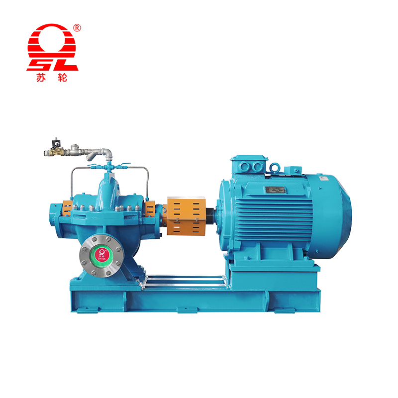
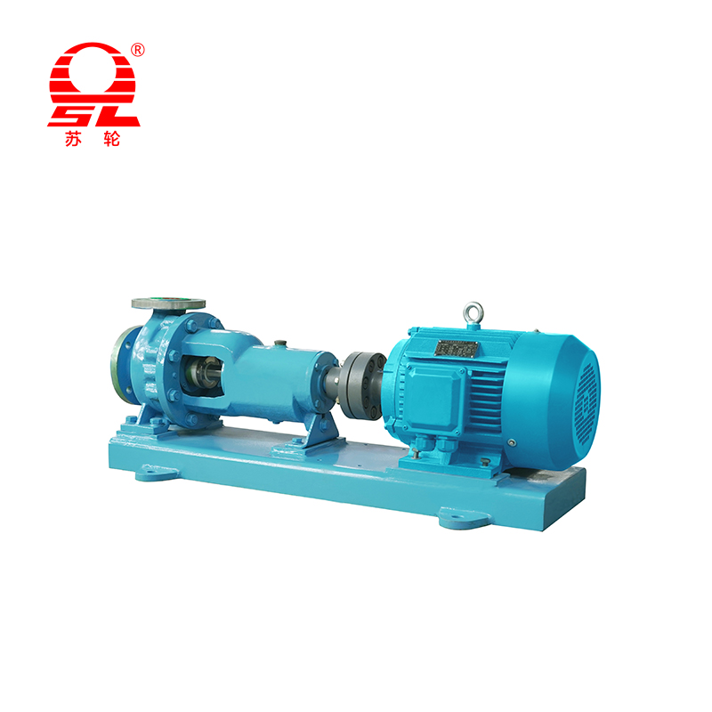 IH Series Horizontal Chemical Centrifugal PumpStainless-steel flow-through parts and ISO2858 dimensions suit corrosive process duties where material selection and suction performance must be assessed together.View Product →
Where the duty includes aggressive or volatile liquids, the suction calculation should use the highest operating temperature and the lowest expected level. If the process can be upset by a blocked strainer, a low-NPSHr impeller and a generous suction line are more useful than a narrow guarantee based on clean conditions.
Good hydraulic selection can be undone by a poor installation. The suction side should be short, direct, and free of high points. A concentric reducer installed flat-side down can create an air pocket; an eccentric reducer with the flat side on top is usually preferred. A strainer should be selected for the dirty pressure drop, and a vacuum gauge should be installed close to the suction flange so the operator can see when the margin is being consumed.
For a flooded suction, the pump should be vented and the suction valve opened fully before the motor starts. For a suction-lift installation, the priming chamber and suction line must be filled and checked for air leaks. A worn seal, a loose flange gasket, or a cracked priming line can allow air into the suction and make a self-priming pump behave as if it has lost its prime. The details matter because a self-priming pump does not create NPSH; it uses the liquid in the casing to establish the suction, and it remains bound by the same vapor-pressure limit as any other centrifugal pump.
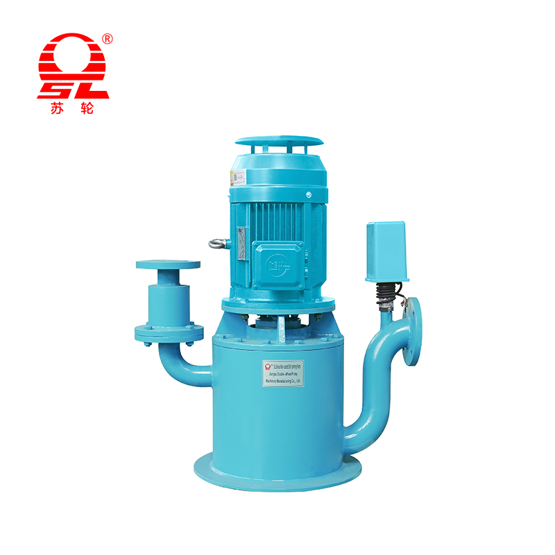
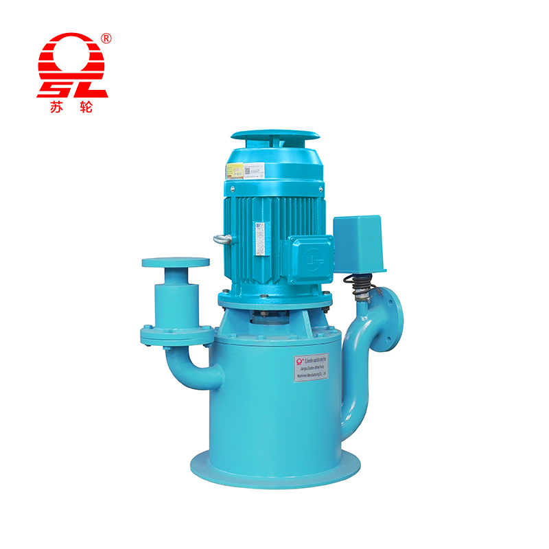 WFB Series Seal-Free Self-Priming PumpSeal-free, self-priming design with up to 7.0 m lift and under 150 s priming time; useful where seal leakage and repeated priming are concerns.View Product →
A mechanical-seal self-priming pump can be a good choice for sump, drainage, and transfer duty when the suction line is properly sized and the seal is kept wet. The mechanical-seal self-priming pump arrangement should still be reviewed for air tightness, priming time, and minimum submergence. If the lift is close to the pump limit, a vertical long-shaft or submersible arrangement may remove the suction-lift problem entirely.
Cavitation is easier to prevent than to correct after damage. The first signs are often changes in sound and vibration, followed by a gradual loss of head or flow. A pump that was quiet at commissioning but becomes noisy after a strainer change, a tank level change, or a temperature increase is giving a useful warning. Record the suction pressure, discharge pressure, flow, and liquid temperature at the same time so the NPSHa can be recalculated from field data.
| Symptom | Likely NPSH cause | Field check | Corrective action |
|---|---|---|---|
| Crackling noise at the casing | Vapor bubbles collapsing at the impeller eye. | Compare suction vacuum with the design value. | Raise level, reduce flow, or revise suction piping. |
| Vibration and unstable head | Intermittent cavitation or air entrainment. | Check strainer differential pressure and seal leakage. | Clean the strainer, seal air leaks, and vent the casing. |
| Loss of prime | Suction lift beyond the self-priming limit. | Check foot valve, priming chamber, and suction joints. | Reduce lift or change to a submerged arrangement. |
| Impeller eye erosion | Long-term operation below the NPSH margin. | Inspect wear pattern and review operating history. | Increase margin and review material selection. |
| Head drop at high flow | NPSHr rises while NPSHa falls. | Record flow, suction pressure, and temperature together. | Limit maximum flow or increase suction pipe size. |
Do not use a larger motor as the first response to cavitation. A larger motor may keep the pump running while the impeller continues to lose material. The correct response is to restore the NPSH margin: raise the liquid level, cool the liquid if the process allows, reduce flow, open a suction valve, clean the strainer, or change the pump arrangement.
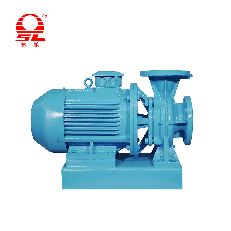
Different pump types solve different suction problems. A horizontal centrifugal pump is easy to inspect and maintain, but it needs a suction system that provides adequate NPSHa. A self-priming pump can handle a suction lift after priming, but it is not immune to cavitation. A vertical long-shaft pump removes the suction lift by placing the impeller below the liquid level, yet it introduces submergence and column-design requirements. A submersible sewage pump avoids suction lift entirely but must be selected for the sump geometry and the risk of air entrainment.
| Pump type | NPSH advantage | Watch-out |
|---|---|---|
| Horizontal centrifugal | Simple inspection and broad hydraulic coverage. | Suction lift and long suction lines reduce NPSHa. |
| Self-priming centrifugal | Can establish prime from a suction lift. | Priming time, air leaks, and lift limit must be checked. |
| Vertical long-shaft | Impeller can be placed below the liquid surface. | Minimum submergence and column losses need review. |
| Submersible sewage | No external suction line in a wet well. | Vortexing, rag loading, and sump level affect reliability. |
| Chemical process centrifugal | Alloy and seal options can match the liquid. | Vapor pressure and material compatibility must be accurate. |
For deep pits, tanks, and sumps, a vertical long-shaft arrangement often gives a more stable NPSH situation than a pump mounted above the liquid, provided the submergence and column design are correct. The suction condition should be checked at the lowest operating level, not only at the normal level. A vertical versus horizontal comparison is useful, but the decisive data are the site elevation, liquid temperature, minimum level, and suction losses.
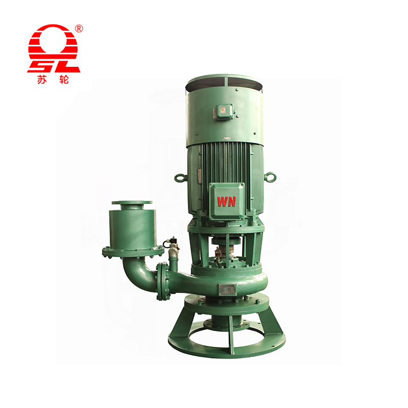
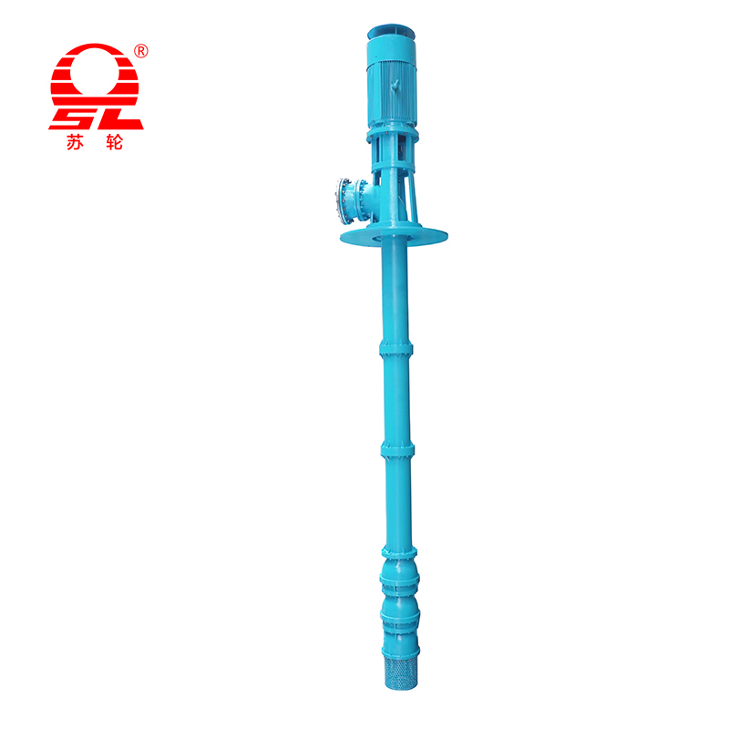 SLC Series Compact Vertical Long Shaft PumpSubmerged impeller and vertical single-tube layout suit deep pits and sumps, where minimum level, submergence, and suction losses drive the NPSH review.View Product →
The vertical versus horizontal pump NPSH behavior is often summarized too simply. Vertical pumps can avoid a long suction line, but they still cavitate if the liquid level is too low or the column is poorly vented. Horizontal pumps can be reliable when the suction system is generously sized and the NPSHa is calculated at the worst condition.
A pump order should include enough information for the supplier to confirm NPSHr at the actual duty, not only at the best efficiency point. The buyer should also state the consequences of cavitation: product contamination, lost production, seal damage, impeller erosion, or safety risk. That information helps determine whether a standard margin is enough or whether a low-NPSHr design is justified.
Liquid data
Provide density, viscosity, vapor pressure, temperature range, solids content, dissolved gas, and chemical concentration. Use the maximum temperature for NPSH.
Site data
State elevation, minimum and maximum tank level, pump centerline elevation, and whether the suction is flooded or lifted.
Suction layout
Include pipe diameter, length, elbows, valves, strainer, foot valve, and straight length before the pump inlet.
Duty range
Give normal, maximum, and minimum flow. Ask for NPSHr at each expected condition, not only at rated flow.
Test requirement
Request the NPSHr test basis, acceptable head-drop criterion, speed, impeller diameter, and witness options.
Material and seal
Confirm impeller, casing, wear ring, shaft, and seal materials against the liquid and the risk of cavitation damage.
Also ask for the curve at the supplied impeller diameter and the speed that will actually be used. A guaranteed NPSHr at a different speed or impeller trim is not a useful guarantee. If the pump will operate in parallel, request the NPSHr for the maximum combined flow and confirm how the suction header pressure changes when the second pump starts.
NPSH is the absolute pressure energy available at the pump suction after vapor pressure, static lift, and friction losses are taken into account. NPSH available belongs to the system. NPSH required belongs to the pump. Cavitation becomes likely when the available value falls to or below the required value without an adequate margin.
For many clean-water applications, a margin of at least 0.5 m to 1.0 m or 10% to 15% of NPSHr is a practical starting point. Hot liquids, volatile chemicals, high-energy impellers, abrasive slurries, and critical services often need a larger margin because the consequences of cavitation are more severe and the operating conditions can change.
NPSHr changes with flow, and suction friction rises with flow. A pump may be safe at its normal duty but cavitate at maximum flow because the required suction head increases while the available suction head decreases. The review should cover the maximum expected flow, not only the design point.
Yes. Self-priming refers to the ability to establish prime from a suction lift; it does not remove the vapor-pressure limit. A self-priming pump can cavitate if the lift is too high, the liquid is hot, the suction line leaks air, or the strainer is blocked. Priming time and air tightness are part of the NPSH review.
It can, because the impeller may be placed below the liquid level and the long suction line is eliminated. However, minimum submergence, vortexing, column losses, and low liquid level still affect NPSHa. A vertical pump is not automatically immune to cavitation.
As temperature rises, vapor pressure rises and the available pressure head above vapor pressure falls. Water near its boiling point has very little NPSH margin even at a modest suction lift. The calculation must use the highest expected pumping temperature, not the temperature at commissioning.
NPSHa is calculated from the system: atmospheric pressure, vapor pressure, static lift, and suction friction. NPSHr is a pump characteristic read from a tested curve at a stated flow and speed. The margin is NPSHa minus NPSHr at the same operating condition.
Increasing speed usually makes cavitation worse because NPSHr tends to rise and suction velocity increases. The better options are to raise the liquid level, reduce flow, enlarge the suction pipe, remove suction restrictions, lower the pump, or select a low-NPSHr impeller.

+86-0523- 84351 090 /+86-180 0142 8659


Add 1: Hongguang Industrial Park, Jingjiang City, Jiangsu Province, China
Add 2: No.68, Xinyi Road, Industrial Park, Jingjiang City, Jiangsu Province, China
+86-0523- 84351 090
+86-180 0142 8659
+0523-8435 5588