language
  русский
 عربى
عربى Indonesia
Home / Blog / Industry News / How Do Centrifugal Pumps Work and What Are Their Main Applications
News


 2026.07.16
 Industry News
Working Principle, Efficiency, Selection and Maintenance
A centrifugal pump transfers liquid by converting the rotational energy of an impeller into liquid velocity and pressure. This operating principle makes centrifugal pumps suitable for water supply, circulation, cooling, irrigation, drainage, processing and many other applications that require continuous and stable liquid movement.
Selecting the correct centrifugal pump requires more than comparing motor power or outlet diameter. Flow rate, total head, liquid properties, suction conditions, operating time and system resistance must be evaluated together.
The search question “what is centrifugal pump” usually refers to a rotodynamic pump in which an impeller rotates inside a casing. Liquid enters near the center of the impeller, moves outward through the impeller passages and leaves the pump at a higher velocity.
The pump casing then guides the moving liquid toward the discharge connection. Part of the liquid velocity is converted into pressure. The generated flow and head depend on impeller diameter, rotational speed, casing geometry, liquid properties and the resistance of the connected piping system.
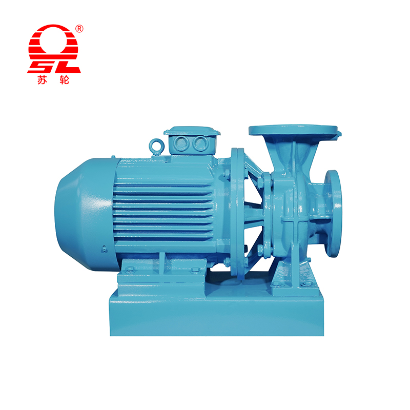
A centrifugal water pump is commonly used for clean water or liquids with physical properties close to water. Special impeller, casing and sealing arrangements may also be used for corrosive liquids, hot liquids, wastewater, suspended solids or process fluids.
Liquid enters through the suction pipe and moves toward the center of the impeller. The suction system must provide sufficient pressure to keep the liquid from vaporizing before it reaches the impeller.
The motor rotates the pump shaft and impeller. Liquid trapped between the impeller vanes gains velocity and moves from the impeller eye toward the outer diameter.
Liquid leaving the impeller enters a volute or diffuser. The expanding flow passage reduces velocity and converts part of the kinetic energy into pressure energy.
The developed pressure pushes the liquid through pipes, valves, filters, heat exchangers, spray equipment or other connected components.
The pump does not operate independently at its maximum flow or maximum head. Its actual operating point is where the pump performance curve intersects the system resistance curve.
How Do Centrifugal Pumps Work?
How do centrifugal pumps work can be explained through energy conversion. The motor supplies mechanical power to the shaft. The impeller transfers this power to the liquid. The casing controls the direction of flow and converts velocity into usable pressure.
The suction side does not pull liquid in the same way as a positive displacement pump. Liquid enters because the pressure at the impeller eye becomes lower than the pressure available at the source. Atmospheric pressure, tank pressure or flooded suction conditions then move liquid into the pump.
Centrifugal pump efficiency expresses how effectively the pump converts mechanical input power into useful hydraulic power. Efficiency is influenced by hydraulic losses, mechanical friction, internal leakage, impeller design and the selected operating point.
A larger pump is not automatically more efficient for every system. A pump operating far below or above its best efficiency point may consume unnecessary power, generate unstable flow and experience greater mechanical stress.
Impeller profile, vane angle, casing passage and internal clearances affect energy loss.
Operation close to the best efficiency point generally supports smoother hydraulic performance.
Higher viscosity can reduce flow, head and overall efficiency compared with clean water operation.
Impeller erosion, enlarged clearances and damaged wear rings increase internal recirculation.
Usually occurs near the lowest head area of the curve. It does not represent the normal operating flow at every pressure condition.
Usually occurs near shutoff or very low flow. Continuous operation at this point can create heat and internal recirculation.
Represents the intended combination of flow and head used to evaluate motor power, efficiency and operating stability.
Viscosity increases hydraulic resistance and can reduce pump capacity and efficiency.
Excessive air can interrupt stable flow and reduce the pressure developed by the impeller.
Long operation below the recommended range may cause recirculation, vibration and temperature rise.
Hard particles may wear the impeller, casing, wear rings and mechanical seal surfaces.
Centrifugal Water Pump Selection
Define the actual liquid volume required per minute or per hour. Include normal demand and short-duration peak demand.
Add vertical elevation, required outlet pressure and friction loss from pipes, valves, fittings and equipment.
Confirm whether the pump has flooded suction, suction lift, pressurized inlet or a long suction pipeline.
Record temperature, density, viscosity, corrosiveness, gas content and suspended solids.
Verify voltage, frequency, phase, available current, motor protection and installation environment.
Determine whether the pump requires pressure control, level control, variable speed or automatic duty rotation.
| Pump Configuration | Structural Characteristic | Typical Operating Requirement | Selection Focus |
|---|---|---|---|
| End-Suction Centrifugal Pump | Liquid enters one side of a single impeller | General water transfer and circulation | Flow, head, alignment and foundation |
| Inline Centrifugal Pump | Suction and discharge connections share a pipeline axis | Building services and compact circulation systems | Pipe support, maintenance space and motor cooling |
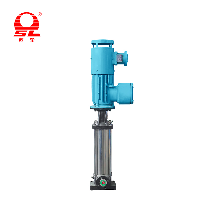
| Multistage Centrifugal Pump | Multiple impellers increase pressure in sequence | Higher-head water supply and process service | Stage number, inlet pressure and axial load |
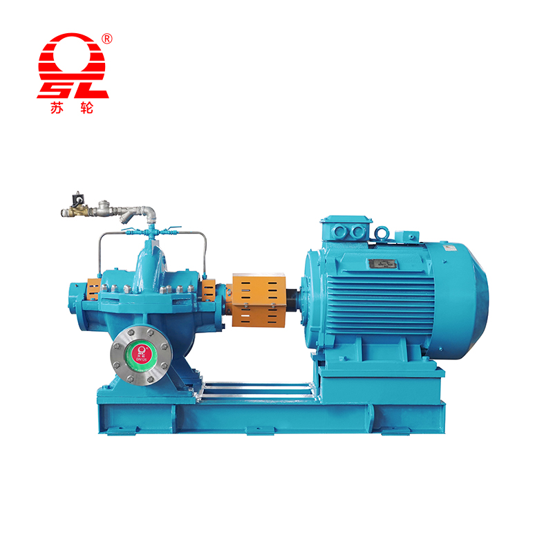
| Double-Suction Centrifugal Pump | Liquid enters both sides of the impeller | Large flow and continuous water movement | Suction layout, balance and installation accuracy |
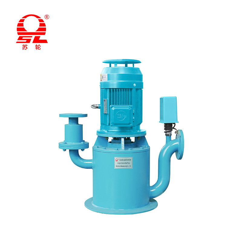
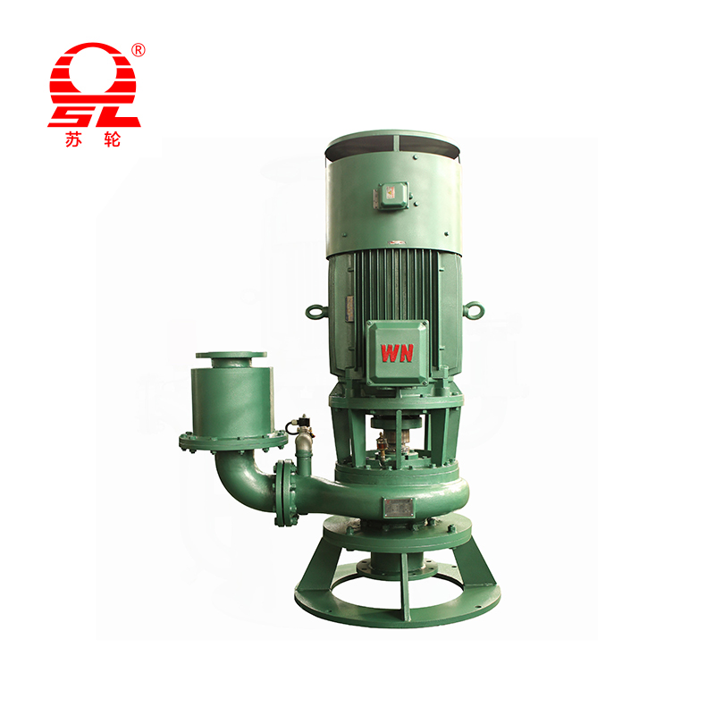
| Vertical Centrifugal Pump | Shaft and hydraulic components are arranged vertically | Tanks, pits, wells and limited-floor-space systems | Installation depth, shaft support and access |
| Self-Priming Centrifugal Pump | Casing retains liquid for air-removal during startup | Above-liquid installation and intermittent transfer | Priming time, suction leakage and retained liquid |
Preventive maintenance should follow the operating environment, liquid characteristics, running hours and pump construction. Inspection frequency may need to increase when handling hot, abrasive or corrosive liquids.
Check casing filling, valve position, shaft movement, rotation direction, suction condition and leakage around seals or pipe connections.
Monitor flow, pressure, motor current, bearing temperature, seal leakage, noise and vibration.
Check bearings, lubrication, coupling alignment, mechanical seals, wear rings, impeller surfaces and fastening bolts.
Inspect for cavitation, blocked suction, dry running, overheating, motor overload or sudden loss of flow.
Drain freezing or corrosive liquid, flush the casing, protect machined surfaces and verify free shaft rotation before reuse.
Empty casing, closed valve, incorrect rotation, blocked inlet or air leakage in the suction line.
Prime the pump, inspect valve position, verify rotation and test suction-pipe airtightness.
Excessive system resistance, worn impeller, blocked filter, air entry or unsuitable rotational speed.
Measure actual head, clean the inlet, inspect wear and compare the operating point with the pump curve.
Cavitation, misalignment, unbalanced impeller, loose foundation or damaged bearings.
Inspect suction pressure, alignment, mounting bolts, bearing condition and impeller cleanliness.
Flow is too high, liquid density is higher than expected, shaft friction or electrical supply is abnormal.
Measure current, verify liquid data, inspect rotating parts and adjust the operating point.
Seal-face wear, dry running, shaft movement, incorrect seal material or installation damage.
Inspect the mechanical seal, shaft sleeve, bearings and liquid compatibility before replacement.
Cavitation occurs when local pressure at the impeller inlet falls low enough for vapor bubbles to form. These bubbles collapse as they move into higher-pressure regions, producing noise, vibration and repeated impact on hydraulic surfaces.
Most standard centrifugal pumps require the casing and suction path to contain liquid before startup. A pump cannot develop stable hydraulic pressure when the impeller is rotating mainly in air.
Brief operation may be permitted for certain startup procedures, but prolonged shutoff operation can increase internal temperature and recirculation. The approved operating instructions should be followed.
Capability depends on the impeller type, passage size and material. Clean-water designs should not be used for large solids or abrasive particles without confirming the permitted limits.
A centrifugal pump follows its performance curve. As system resistance changes, the operating point moves and produces a different combination of flow and head.
Select the pump near the required duty point, reduce unnecessary pipe resistance, maintain internal clearances and use variable-speed control when demand changes significantly.
Possible reasons include suction leakage, falling source level, blocked strainers, cavitation, gas accumulation or a system operating point outside the intended range.
Flow rate, total head, suction pressure, liquid temperature, viscosity, solid size, installation position, operating hours and power conditions help determine the appropriate pump type, impeller structure, casing material, seal arrangement and motor rating.

+86-0523- 84351 090 /+86-180 0142 8659


Add 1: Hongguang Industrial Park, Jingjiang City, Jiangsu Province, China
Add 2: No.68, Xinyi Road, Industrial Park, Jingjiang City, Jiangsu Province, China
+86-0523- 84351 090
+86-180 0142 8659
+0523-8435 5588