English
 русский
 عربى
عربى Indonesia
Heavy Duty Vertical Long Shaft Pump Wholesale


Depth to 30+ m
Up to 12 Stages
ISO 9001:2015
CE Certified
ANSI/HI Compliant
Heavy Duty Vertical Long Shaft Pump
The VLS series delivers massive flow capacity and high multi-stage head from the deepest sumps, pits, and intake basins — with the motor permanently above the flood line for instant, reliable start-up in every emergency or continuous-duty scenario. Engineered column-by-column to your exact installation depth, the VLS series is the definitive solution for mine dewatering, flood control, cooling water intake, and heavy industrial sump drainage worldwide.
Product Introduction
Deep-Reach Power, Engineered for the Most Demanding Installations
A comprehensive technical overview of the VLS series Heavy Duty Vertical Long Shaft Pump — purpose-built for deep sump, pit, and underground fluid transfer across the world's harshest industrial environments.
The Heavy Duty Vertical Long Shaft Pump is a specialized class of centrifugal pump engineered for applications where the fluid source is located far below the pump motor — typically in deep sumps, flooded excavations, underground storage pits, mine shafts, cooling water intake basins, and municipal wet wells. Unlike conventional horizontal pumps that must be installed at or near fluid level, the VLS series suspends a column pipe assembly of any required length directly into the liquid, while the motor remains safely above the flood line. This fundamental configuration advantage makes the VLS series uniquely suited to applications where surface-mounted pumps are impractical, unsafe, or impossible.
The architecture of the VLS series consists of four principal sub-assemblies: the submersible bowl assembly at the pump inlet, the column pipe and line shaft assembly that transmits torque from motor to impeller over distances from 1 meter to over 30 meters, the discharge head that supports the entire weight of the suspended assembly and routes flow to the discharge piping, and the driver unit — typically a solid-shaft or hollow-shaft vertical electric motor, diesel engine drive, or right-angle gear drive for non-vertical motor configurations. This modular architecture allows column lengths to be precisely engineered to match the depth of any installation, with no compromise to hydraulic performance.
At the heart of the hydraulic design is our multi-stage bowl assembly, which can be configured with one to twelve impeller stages to achieve heads ranging from 15 meters in single-stage units to over 200 meters in high-head multi-stage configurations. Each impeller is precision-cast from high-chrome alloy iron, duplex stainless steel, or bronze depending on the fluid chemistry, and is dynamically balanced to G2.5 precision grade to eliminate vibration even in the longest shaft configurations. The bowl casing geometries are designed and validated using computational fluid dynamics (CFD) to achieve best-efficiency-point (BEP) hydraulic performance across a broad operating range.
The line shaft — the most mechanically critical element of any vertical long shaft pump — is manufactured from high-tensile alloy steel bar stock, straightness-verified to within 0.05 mm per meter, and supported at regular intervals by water-lubricated sleeve bearings (rubber or Babbitt-lined bronze) or oil-lubricated enclosed lineshaft bearings, depending on the pumped fluid compatibility. Water-lubricated bearings are preferred for clean water and slightly contaminated fluids; enclosed oil-lubricated bearings are selected for hydrocarbon, high-temperature, or chemically aggressive fluids where water lubrication would contaminate the process or be incompatible with the pumped medium. Bearing spacing of 1.5 meters is standard, with closer spacing available for high-speed or critical vibration applications.
Column pipe is available in flanged (standard) or threaded (lineshaft enclosure tube) configurations, in carbon steel, stainless steel SS304/316, and duplex 2205 grades. For highly corrosive environments such as seawater intake, acid mine drainage, or industrial effluent sumps, we offer HDPE column pipe with stainless internal hardware as a cost-effective corrosion solution. All column pipe joints are precision-machined to ensure perfect axial alignment — critical for maintaining shaft-to-bearing clearances over long column depths.
The VLS series discharge head is the structural backbone of the installation, designed to carry the combined weight of the column assembly, motor, and hydraulic axial thrust load. Fabricated from cast iron or carbon steel plate, it is designed in accordance with ANSI/HI 2.1–2.6 Vertical Pump Standards and HIS (Hydraulic Institute Standards) for vertical pump applications. The discharge head includes provisions for motor mounting (solid-shaft or hollow-shaft adapter), discharge flange, lifting lugs, and access ports for shaft adjustment. For diesel-driven applications, a right-angle gear drive adapter head is available for horizontal engine configurations.
Applications span the full spectrum of heavy industry: flood control pump stations, mine dewatering, power plant cooling water intake, petrochemical sump drainage, municipal water intake from rivers and lakes, irrigation lift stations, and condensate return systems. In flood control and municipal applications, the ability to install the motor above the maximum flood level while keeping the bowl assembly permanently submerged means the pump is always primed and ready for instant start — a critical capability for emergency dewatering operations.
Every VLS series pump is manufactured under our ISO 9001:2015 certified quality management system and undergoes factory performance testing on our vertical pump test stand — capable of simulating column depths up to 15 meters — before shipment. Test data including head-capacity (H-Q) curve, power curve, efficiency curve, and NPSHr values are provided in the factory test report. For export projects, full documentation including CE Declaration of Conformity, material test certificates, hydrostatic test certificate, and dimensional inspection records are included in the shipping documentation package.
Column depth from 1 m to 30+ m — fully engineered to installation
1 to 12 impeller stages — head up to 200 m
Water-lube or oil-lube enclosed lineshaft bearing options
G2.5 dynamically balanced impellers — vibration-free long-shaft operation
Motor remains above flood line — always primed, instant start
ANSI/HI 2.1–2.6 compliant design; ISO 9001:2015 certified
Carbon steel / SS304 / SS316 / Duplex 2205 / HDPE column options
Factory H-Q performance test with full certification documentation
Technical Data
Technical Specifications
Full performance parameters across the VLS Heavy Duty Vertical Long Shaft Pump series — from compact single-stage dewatering units to large-scale multi-stage high-head installations.
| Parameter | Specification |
|---|---|
Flow Rate Range | 10 m³/h – 5,000 m³/h |
Total Head Range | 15 m – 200 m (multi-stage) |
Column (Setting) Depth | 1.0 m – 30+ m (custom-engineered) |
Number of Stages | 1 – 12 stages |
Bowl Diameter | 150 mm – 1,200 mm |
Discharge Flange Size | DN 80 mm – DN 800 mm |
Motor Power Range | 5.5 kW – 2,000 kW |
Supply Voltage | 380 V / 6 kV / 10 kV (50 Hz / 60 Hz) |
Rated Speed | 485 – 1,480 rpm (4-pole to 12-pole) |
Lineshaft Bearing Type | Water-lubricated rubber / Oil-lubricated enclosed bronze |
Lineshaft Bearing Spacing | Standard 1,500 mm; closer spacing on request |
Impeller Material | High-Chrome Alloy Iron, Duplex 2205 SS, Bronze, SS316 |
Column Pipe Material | Carbon Steel, SS304, SS316, Duplex 2205, HDPE |
Operating Temperature | −10 °C to +120 °C |
Max Working Pressure | Up to 2.5 MPa (PN25) |
Solids Handling | Clean to slightly turbid; abrasive-liner option available |
Explosion-Proof Option | Ex d IIB T4 / Ex d IIC T4 (ATEX / IECEx) |
Flange Standard | GB / DIN / ANSI / JIS (customizable) |
Design Standard | ANSI/HI 2.1–2.6; ISO 9001:2015; CE |
Why Choose VLS
Core Advantages
Eight structural, hydraulic, and operational advantages that make the VLS Heavy Duty Vertical Long Shaft Pump the preferred choice for deep-installation fluid handling across mining, power, municipal, and heavy process industries.
Custom Column Depth Engineering
No two deep-sump installations are identical. The VLS series is not a shelf product — every unit is engineered to your exact sump depth, from 1 meter to over 30 meters. Column pipe sections, lineshaft segments, and bearing spacings are precisely calculated and factory-assembled for your specific installation geometry, eliminating field cutting, improvised joints, and alignment uncertainty.
Multi-Stage High Head Capability
A single VLS pump can be configured with up to 12 hydraulic stages to achieve discharge heads exceeding 200 meters. This eliminates the need for booster pump stations in deep-mine drainage, high-rise building water supply, and long-distance irrigation lift scenarios — reducing capital cost, installation space, and system complexity significantly.
Motor Above Flood Level — Always Primed
Because the motor sits on the discharge head above the installation surface, it is permanently protected from flooding — even when the sump overflows or the installation area is inundated. The bowl assembly remains permanently submerged and primed, allowing instantaneous start with no priming delay — a mission-critical advantage in flood-control and emergency dewatering applications.
G2.5 Dynamically Balanced Impellers
In long-shaft pump systems, impeller imbalance is amplified through the column and causes excessive bearing wear, shaft fatigue, and vibration transmission to the discharge head structure. Every VLS impeller is dynamically balanced to ISO 1940 G2.5 grade — the same standard used in industrial turbomachinery — ensuring smooth, vibration-free operation even at column depths exceeding 20 meters and high motor speeds.
Water- or Oil-Lubricated Lineshaft Options
The lineshaft bearing lubrication system is selected to match the pumped fluid. Water-lubricated rubber sleeve bearings use the pumped liquid itself as the lubricant — perfect for clean water, irrigation, and municipal intake applications. Enclosed oil-lubricated lineshaft tube bearings isolate the shaft from the process fluid — essential for hydrocarbon, chemical, or contaminated mine water applications where cross-contamination must be prevented.
Multiple Driver Configurations
The VLS discharge head accommodates solid-shaft vertical motors, hollow-shaft vertical motors (with adjustable impeller position), right-angle gear drives for horizontal diesel or gas engine drivers, and variable-speed hydraulic drives. This flexibility allows the same bowl-and-column assembly to be re-powered with a different driver type in the field without replacing the hydraulic components.
Factory H-Q Performance Certification
Every VLS pump is tested on our vertical pump performance test stand before shipment. The factory test generates a certified head-capacity (H-Q) curve, power consumption curve, efficiency curve, and NPSHr data at multiple operating points. This documentation gives project engineers the confidence that the delivered unit exactly matches the specified performance — eliminating commissioning surprises and disputes.
Field-Serviceable Modular Design
The VLS column assembly can be pulled from the sump in sections for inspection or component replacement without dewatering the pit or removing the discharge head. Bowl assembly, impeller stages, lineshaft segments, and sleeve bearings are all independently field-replaceable by a two-person crew using standard lifting equipment. Standardized thread and flange connections ensure 100% component interchangeability with future replacement parts.
Use Cases
Primary Applications
The VLS Heavy Duty Vertical Long Shaft Pump is deployed across the world's most demanding deep-installation fluid handling scenarios — wherever the fluid source lies far below the surface and reliability is non-negotiable.
Mine Dewatering
The definitive pump for underground and open-pit mine dewatering. Long column depths reach flooded levels in deep shafts; abrasion-resistant impeller liners and high-chrome bowl materials handle grit-laden mine water. Multi-stage configurations provide the high head needed to lift water from deep workings to surface collection points without intermediate booster stations.
Flood Control Pump Stations
Installed in permanent flood control pump stations where the motor must remain above the design flood level while the bowl assembly handles the lowest sump levels. Instant start capability without priming means the pump is operational the moment the control system triggers — critical in urban flood events where minutes matter.
Power Plant Cooling Water Intake
Large-bowl VLS pumps handle river, lake, and coastal intake for once-through and recirculating cooling water systems in thermal, gas-fired, and nuclear power facilities. High flow rates (up to 5,000 m³/h per unit), low sump NPSH conditions, and continuous 24/7 duty cycles are all within the VLS design envelope. Bronze impellers resist biofouling in open waterway intake applications.
Petrochemical Sump Drainage
Enclosed oil-lubricated lineshaft configuration prevents cross-contamination between process hydrocarbon fluids and bearing lubricants. ATEX-certified explosion-proof motors ensure safe operation in classified hazardous areas. SS316 or Duplex 2205 column and bowl materials withstand hydrocarbon-contaminated water, sulfide-bearing liquids, and corrosive condensate in refinery and chemical plant sumps.
Municipal Water Intake and Supply
River intake, lake abstraction, and reservoir pump stations for municipal water treatment and supply systems. The VLS motor-above-flood design eliminates the risk of motor damage during high-water events. Large flow capacity and multi-stage capability serve both low-head high-volume river intake and high-head elevated reservoir fill applications from a single pump platform.
Irrigation Lift Stations
Agricultural canal lift stations and river-to-field irrigation pumping where intake levels fluctuate seasonally. VLS pumps handle variable submergence depth gracefully — the fixed column design keeps the bowl in optimal operating range regardless of surface water level variation up to the column depth limit. High-efficiency bronze or cast iron impellers minimize power consumption over long annual operating seasons.
Construction and Infrastructure Dewatering
Deep foundation excavations, tunnel boring operations, underground car parks, and subway station construction require sustained dewatering from depths that submersible pumps struggle to handle reliably. The VLS motor-above-ground design allows full electrical access and maintenance without entering a flooded excavation, dramatically improving safety and maintenance convenience on construction sites.
Steel, Metallurgy and Heavy Manufacturing
Scale pit dewatering, rolling mill cooling water recirculation, quench tank drain systems, and process water lift from below-grade sumps in steel mills and heavy manufacturing plants. High-temperature variants (up to 120 °C) handle hot process water; abrasion-resistant high-chrome impellers withstand suspended mill scale and metallic particles in the pumped liquid.
Head-to-Head
Performance Comparison
A detailed comparison of the VLS Heavy Duty Vertical Long Shaft Pump against submersible pumps and horizontal centrifugal pumps for deep-installation fluid handling applications.
| Feature / Criteria | VLS Vertical Long Shaft Pump | Submersible Pump | Horizontal Centrifugal Pump |
|---|---|---|---|
| Motor Location | Above flood level — fully accessible | Submerged — requires dewatering for access | Above floor — accessible |
| Installation Depth Range | 1 m – 30+ m (custom-engineered) | Deep but limited by cable length and heat | Limited to ~7 m suction lift maximum |
| Priming Required | None — bowl permanently submerged | None — fully submerged | Required — suction pipe must be primed |
| Motor Maintenance Access | Immediate — no dewatering needed | Must pull entire unit from sump | Immediate access |
| Multi-Stage High Head | Up to 12 stages — 200 m head | Limited stage count — heat dissipation constraint | Multi-stage available but separate unit needed |
| Motor Flood Protection | Complete — motor always above water | Dependent on seal integrity — risk at seal failure | Vulnerable if installation area floods |
| Large Flow Capacity | Up to 5,000 m³/h single unit | Limited by motor heat and cable size | High flow possible but installation constraints |
| Variable Sump Level Tolerance | Bowl fixed in sump — handles level variation | Can auto-adjust with level — float control | Sensitive to suction head changes |
| Maintenance Without Crane | Column pull requires lift equipment | Pulling cable and pump requires hoist | In-place maintenance possible |
| ATEX / Hazardous Area Use | Full ATEX motor options — Ex d IIB/IIC | Limited ATEX submersible options available | Standard ATEX motor — widely available |
Expert Tips
Usage Tips and Best Practices
Maximize the operational reliability, service life, and hydraulic performance of your VLS Heavy Duty Vertical Long Shaft Pump with these field-proven recommendations from our engineering team.
1
Sump Geometry and Minimum Submergence
The bowl assembly intake must always remain submerged by at least 0.5 m (1.0 m recommended) below the minimum operating water level to prevent vortex formation and air entrainment at the inlet. Design the sump geometry in accordance with ANSI/HI 9.8 Pump Intake Design standards. An incorrectly shaped sump — too narrow, too shallow, or with asymmetric inflow — is the most common cause of vibration and performance degradation in vertical pump installations.
2
Impeller Setting Adjustment at Commissioning
For hollow-shaft motor configurations, the impeller must be set to the correct axial position at commissioning using the adjusting nut at the top of the motor. Incorrect impeller setting is the leading cause of premature bowl wear in vertical long shaft pumps. Follow the factory-provided setting dimension and verify actual position by measuring from the top of the adjusting nut to a reference point on the discharge head, then lock the adjusting nut with the lock nut before starting.
3
Water-Lubricated Bearing Pre-Lubrication
For water-lubricated lineshaft bearing pumps, the lineshaft sleeve bearings must be pre-lubricated with clean water before every start — especially after any extended downtime — to prevent dry-running bearing damage during the few seconds before pumped liquid reaches the upper bearings. This is done via a pre-lube water connection at the discharge head that feeds clean water down the column tube before the pump starts. The EACS module can automate this pre-lube cycle on a timer interlock.
4
Shaft Alignment and Coupling Inspection
After the first 100–200 hours of operation, re-check and re-torque all column pipe and shaft coupling bolts to specification. Thermal cycling and initial settling can cause slight relaxation in flanged column joints. Misaligned or loose shaft couplings are a primary source of vibration and accelerated bearing wear in long-shaft systems. Use a dial indicator on the discharge head bearing housing to verify that shaft runout remains below 0.05 mm after any maintenance procedure involving column disassembly.
5
Vibration Baseline and Monitoring
Record vibration levels (velocity in mm/s RMS and acceleration in g) at the discharge head bearing housing in both horizontal axes immediately after commissioning. This baseline measurement is the reference standard for all future condition monitoring. If vibration increases by more than 50% above baseline, investigate immediately — causes include impeller wear, bearing wear, cavitation, column joint loosening, or impeller foreign object ingestion. ISO 10816 limits for vertical pumps are the appropriate benchmark.
6
Column Pull and Inspection Schedule
Plan a full column pull inspection every 3–5 years for continuous-duty installations, or every 10,000 operating hours. During a column pull, inspect: sleeve bearing ID wear (replace if worn beyond 0.5 mm above nominal clearance), impeller vane profiles for erosion, column pipe interior for corrosion or scaling, lineshaft for bending (roll on a flat surface — any visible runout requires replacement), and all O-ring and gasket seating surfaces for corrosion pitting.
7
Thrust Bearing Lubrication (Motor)
The vertical motor thrust bearing carries the full downward hydraulic axial load plus the rotating assembly weight — a combined load that can be substantial in multi-stage, deep-column installations. Ensure the thrust bearing is lubricated with the correct grade of oil (typically ISO VG 68 or VG 100 turbine oil) to the correct fill level as specified in the motor maintenance manual. Overheating of the thrust bearing is the most common motor failure mode in vertical long shaft pump applications and is almost always caused by incorrect oil grade, low oil level, or cooling air restriction.
8
Operating Range and Minimum Flow
Vertical long shaft pumps are highly sensitive to off-BEP operation. Never operate below 60% of BEP flow rate for extended periods without a minimum flow bypass line. Low-flow operation causes internal recirculation, hydraulic surging, elevated radial loads on the lineshaft, and rapid impeller wear. If the process requires frequent low-flow operation, specify a VFD speed controller to reduce pump speed proportionally — this is far more efficient and less damaging than throttling the discharge valve.
FAQ
Frequently Asked Questions
Clear, engineering-level answers to the most common questions buyers, project engineers, and site managers ask about the VLS Heavy Duty Vertical Long Shaft Pump series.
What is the maximum column (setting) depth available?
Standard VLS series configurations are available with column depths from 1 meter to 30 meters in modular 1.5-meter column pipe sections. For deeper applications — such as deep mine shafts or municipal intake wells — custom column depths beyond 30 meters are engineered on a project-specific basis, with additional shaft support analysis to ensure safe operation. Provide your required submergence depth and we will calculate the required column configuration and confirm feasibility.
What is the difference between a solid-shaft and hollow-shaft motor configuration?
A solid-shaft motor drives the pump lineshaft through a rigid mechanical coupling at the discharge head. The shaft-to-impeller axial position is fixed at assembly and cannot be adjusted in the field. A hollow-shaft motor passes the pump lineshaft directly through the motor shaft bore — the impeller axial position is adjusted via an adjusting nut at the top of the motor, allowing precise field setting. Hollow-shaft configurations are preferred for most applications because they allow impeller position optimization after installation, compensating for any dimensional variation in the sump depth or bowl stack height.
When should I choose water-lubricated versus oil-lubricated lineshaft bearings?
Choose water-lubricated bearings for: clean or lightly turbid water, municipal intake, irrigation, flood control, and cooling water applications where a small amount of bearing lubricant entering the process is acceptable. Choose enclosed oil-lubricated bearings for: hydrocarbon fluids (where water would contaminate the process or emulsify), chemical process fluids incompatible with rubber bearing materials, high-temperature fluids (above 60 °C), abrasive mine water with high solids content, and any application where cross-contamination between lubricant and process fluid cannot be tolerated.
Can the pump handle fluids containing sand or grit?
Yes, with the correct material selection. For fluids with moderate sand and grit content (mine water, river intake during flood events), we recommend high-chrome alloy iron impellers and wear plates, which offer 3–5× the abrasion resistance of standard cast iron at only a moderate cost premium. For highly abrasive slurries, rubber-lined bowl options are available. Water-lubricated rubber sleeve bearings tolerate moderate grit in the pumped liquid. For heavy-solids applications, specify enclosed oil-lubricated lineshaft bearings to keep the bearing surfaces isolated from the abrasive fluid.
How is the pump column assembled and installed on site?
The VLS pump ships in sub-assembled sections: the bowl assembly (pre-assembled with all impeller stages), 1.5-meter column pipe sections, lineshaft segments, and the discharge head. Installation proceeds from the bottom up: the bowl is lowered into the sump, column pipe sections are added one by one using a temporary support plate at the sump rim, with lineshaft segments coupled inside the column as it is built up. The discharge head is installed last and bolted to the sump structure. A mobile crane or chain hoist of adequate capacity is required. Full illustrated installation drawings and a written installation procedure are provided with every unit.
Can I add more stages later to increase the head?
Yes, within design limits. The VLS bowl assembly is modular — additional impeller stages can be added by pulling the bowl and inserting additional stage sections, provided the discharge head and column pipe are rated for the higher working pressure that the additional stages will generate, and the motor has sufficient power margin. Before ordering additional stages, submit your current configuration details and we will assess whether the existing column, discharge head, and motor can accommodate the additional stages or whether some components require upgrading.
Is an explosion-proof (ATEX) motor option available?
Yes. ATEX-certified explosion-proof vertical solid-shaft and hollow-shaft motors in Ex d IIB T4 and Ex d IIC T4 enclosures are available for Zone 1 and Zone 2 hazardous area classifications. IECEx certification is also available for projects in Australia and other IECEx-adopting countries. For petrochemical sump drainage and hydrocarbon processing applications in classified areas, please specify the hazardous area zone, gas group, and temperature class in your enquiry so the correct certified motor can be selected.
What is included in the factory performance test?
Every VLS pump undergoes a full factory performance test on our vertical pump test stand before shipment. The test generates a certified head-capacity (H-Q) curve with a minimum of five measured operating points from shut-off head to maximum flow, a shaft power consumption curve, an overall efficiency curve, and NPSHr data. A hydrostatic pressure test at 1.5× rated working pressure is also performed. Test certificates, signed by our QC manager, are included in the shipping documentation package. Third-party witness testing (Bureau Veritas, SGS, TÜV) is available on request for an additional fee.
Can a diesel engine be used instead of an electric motor?
Yes. The VLS discharge head can be fitted with a right-angle gear drive adapter that accepts drive from a horizontal diesel engine, gas engine, or any prime mover with a horizontal output shaft. This configuration is particularly popular for emergency flood-control pump stations and remote mine dewatering installations where reliable grid power is not available. Specify the required speed ratio, output power, and engine make/model and we will design the appropriate gear drive adapter for your installation.
What is the lead time and minimum order quantity?
Minimum order quantity is 1 unit. Because every VLS pump is custom-engineered to the client's specific column depth, flow, head, and material requirements, lead times are longer than for standard-configuration products. Typical lead time is 30–50 business days for standard materials; 50–70 business days for special alloy (Duplex 2205, Titanium) or ATEX-certified configurations. For urgent mine dewatering emergencies, contact us directly — we maintain a stock of standard bowl assemblies and column components that can significantly reduce lead time for common configurations.
Can your VLS pump replace imported brands such as Flowserve, KSB, or Goulds?
Yes. We have successfully supplied VLS series pumps as direct performance-equivalent replacements for Flowserve VTP, KSB Omega-V, Goulds VIT, and other internationally specified vertical turbine pump brands on mining, power, and municipal projects across Asia, the Middle East, and Africa. Provide us with the original pump's performance data sheet and dimensional outline drawing, and our engineering team will configure a VLS equivalent that matches or exceeds the original hydraulic performance, with ANSI/HI compliant documentation to support project approval.
Company
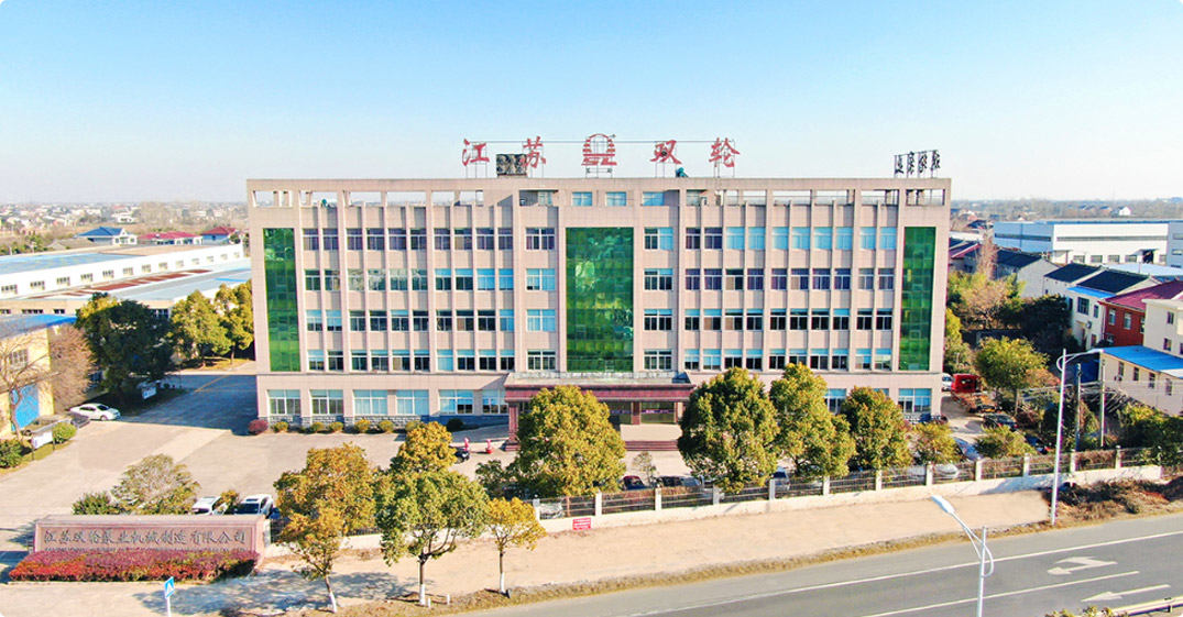
Jiangsu Double-wheel Pump Machinery Manufacting Co.,Ltd.
Jiangsu Double Wheel Pump Machinery Manufacturing Co., Ltd. is China Heavy Duty Vertical Long Shaft Pump Manufacturers and Wholesale Heavy Duty Vertical Long Shaft Pump Factory. The company is located in the scenic Yangtze River bank, Jiangyin Bridge, Beijing-Shanghai Expressway, Shanghai-Nanjing Expressway, Ningtong Expressway, Ningjingyan expressway running through the north and south, the traffic is very convenient, the geographical position is esteemed good. It is a production base specializing in non-sealed self-priming pumps, rain pumps, long-axis liquid pumps, chemical centrifugal pumps, positive displacement pumps and environmental protection equipment and mechanical equipment. The company has two production bases, covering an area of nearly 60,000 square meters, of which the eastern base covers an area of 33,000 square meters, the western base covers an area of 27,000 square meters, six modern production workshops, two installation workshops, a professional test workshop, a variety of mechanical processing equipment more than 160 sets, including a pump comprehensive performance test platform, Can test diameter 32-1200mm, motor power 1.1-1200KW, voltage 380V-10KV of various types of pumps, scientific research, development, manufacturing, processing, promotion, application of its own system. In the past two years, the company has closely followed the national industrial policy, made a big deal about environmental protection, and undertaken a large number of sewage treatment projects, which is unique in the environmental protection industry.
Certificate Of Honor


-
0

Be established in
-
0+

Professional personnel
-
0 million

Registered capital
-
0 ㎡

Plant area
After-Sales Service
Maintenance and Technical Support
Comprehensive lifecycle support from pre-order engineering consultation through installation commissioning, periodic inspection scheduling, long-term spare parts supply, and performance upgrade assistance.
Maintenance and Spare Parts
Engineered for lowest Total Cost of Ownership over a 20-year service life
- Sectional Column Pull Design: The entire column assembly is designed to be pulled from the sump in manageable 1.5-meter sections using standard lifting equipment. A two-person crew can complete a full column pull, impeller inspection, bearing replacement, and re-installation in a single working day — without dewatering the sump or removing the discharge head piping.
- Recommended Spare Parts Package: We provide a project-specific spare parts recommendation list covering: one full set of sleeve bearings (all column positions), one replacement impeller set (matched to the original hydraulic grade), one set of shaft couplings and bolts, and all O-rings and gaskets. Stocking this package on-site ensures that a full column pull can be completed without waiting for parts delivery.
- 100% Dimensional Interchangeability: All VLS components are CNC-machined to tight tolerances. Replacement parts ordered years after the original purchase fit without hand-fitting, grinding, or modification. Our engineering records for your specific pump serial number are retained indefinitely, allowing exact re-manufacture of any component.
- Inspection and Maintenance Schedule: We provide a written, interval-based maintenance schedule specific to your installation — covering daily checks (vibration, noise, bearing temperature), monthly checks (shaft adjustment nut security, oil level for enclosed lineshaft), and annual/multi-year column pull intervals based on fluid quality and operating hours.
- 10-Year Spare Parts Availability Commitment: We guarantee availability of all critical spare parts (impellers, bowls, lineshaft segments, sleeve bearings, shaft couplings) for a minimum of 10 years from the date of original purchase. For large project installations, a bonded spare parts stocking agreement is available.
Professional Technical Support
Expert engineering support from selection through full operational life
- Sump Design Review: Before manufacturing, our engineers review your sump or wet well geometry against ANSI/HI 9.8 Pump Intake Design guidelines. We identify and recommend corrections to any sump geometry issues — flow approach direction, submergence depth, wall clearances, and bell mouth design — that could cause operational problems after installation.
- System Curve and Operating Point Analysis: We calculate your full system curve — including static head, pipe friction, minor losses, and elevation changes — and overlay it on the VLS pump H-Q curve to confirm the actual operating point at both minimum and maximum sump levels. This ensures the pump is selected to operate within 80–110% of BEP flow at all anticipated conditions.
- Installation and Commissioning Support: Full illustrated installation manual, step-by-step commissioning checklist, and impeller setting procedure video are provided with every unit. For major project installations, factory-trained commissioning engineers are available for on-site support — including impeller setting, first-start supervision, vibration measurement, and performance verification against the factory test data.
- 24/7 Remote Troubleshooting: For urgent operational issues — unexplained vibration, reduced flow, unusual noise, motor overcurrent — our technical team responds within 12 hours with a structured diagnostic guide, annotated cross-section drawings, and video consultation. We have diagnosed and resolved complex vertical pump installation issues remotely for clients in Africa, Southeast Asia, and the Middle East without requiring on-site visits.
- Performance Upgrade Engineering: For installed VLS pumps where process requirements have changed — increased flow demand, higher head requirement, or fluid chemistry change — we provide a retrofit engineering assessment. In many cases, the original column and discharge head can be retained while the bowl assembly, impellers, and motor are upgraded to the new duty point, saving the cost of a complete replacement.

+86-0523- 84351 090 /+86-180 0142 8659


Welcome To
Jiangsu Double-Wheel Pump
Add 1: Hongguang Industrial Park, Jingjiang City, Jiangsu Province, China
Add 2: No.68, Xinyi Road, Industrial Park, Jingjiang City, Jiangsu Province, China
Contact
-
Tel:
+86-0523- 84351 090
+86-180 0142 8659 -
FAX:
+0523-8435 5588
- E-mail: