English
 русский
 عربى
عربى Indonesia
Vertical Pipeline Centrifugal Liquid Pump Wholesale


Vertical In-Line Design Up to 1,500 m³/h Space Saving ISO 5199
Vertical Pipeline Centrifugal Liquid Pump
Engineered for direct pipeline installation with vertical orientation. Space-saving design ideal for mechanical rooms, boiler houses, and industrial plants where floor space is limited. Flanges match pipeline dimensions for simple drop-in replacement of existing pumps.
Product Introduction
Vertical In-Line Centrifugal Pump Technology
A comprehensive examination of the engineering, space-saving design, and application benefits of our vertical pipeline centrifugal pump range.
The Vertical Pipeline Centrifugal Liquid Pump is designed for direct installation into existing piping systems. Unlike traditional horizontal pumps that require a large foundation and separate baseplate, the vertical in-line pump mounts directly to the pipeline. The suction and discharge flanges are aligned on the same vertical axis, allowing the pump to be inserted into a straight pipe run. This configuration eliminates the need for elbows, reducing pressure losses and saving significant floor space. The motor is mounted above the pump, further reducing the footprint. These pumps are ideal for mechanical rooms, boiler houses, industrial plants, and any application where floor space is at a premium.
The pump casing is of the vertical in-line design with suction and discharge flanges on the same vertical axis. The casing is supported by the pipeline itself; no additional foundation or baseplate is required. For larger pumps, a support bracket may be attached to the floor or wall to provide additional stability. The casing is manufactured from cast iron, ductile iron, or stainless steel depending on the fluid being pumped. The casing design incorporates a replaceable wear ring to protect the casing from wear at the impeller eye.
The impeller is of the enclosed type, mounted directly on the motor shaft (close-coupled design) or on a separate pump shaft connected to the motor by a flexible coupling (frame-mounted design). The close-coupled design is more compact and eliminates the need for alignment, as the impeller is mounted directly on the motor shaft. The frame-mounted design allows motor replacement without disturbing the pump hydraulics. The impeller is dynamically balanced to ISO 1940 Grade G2.5 to ensure smooth, vibration-free operation. The impeller is available in cast iron, bronze, or stainless steel to suit the fluid being pumped.
The seal chamber is located between the pump casing and the motor or bearing housing. The shaft passes through the seal chamber, with a mechanical seal or gland packing providing the seal against the pumped liquid. For vertical in-line pumps, the mechanical seal is typically of the cartridge type for easy replacement. The seal is located above the pump casing, which helps prevent leakage from damaging the motor or bearings. For high temperature applications, the seal chamber may be jacketed for cooling.
The bearing system for close-coupled pumps is contained within the motor. The motor bearings must support both the motor rotor weight and the hydraulic loads from the impeller. Motors for close-coupled pumps are specified with heavier bearings than standard motors. For frame-mounted pumps, a separate bearing housing is provided. The bearing housing contains the pump bearings (radial and thrust) and is oil or grease lubricated. The bearing housing is supported by the pump casing or by a separate mounting bracket.
The motor is mounted vertically above the pump. For close-coupled pumps, the motor has a special C-face mounting flange that bolts directly to the pump casing. The motor shaft is extended and machined to accept the impeller. Motors are TEFC (Totally Enclosed Fan Cooled) for general purpose applications, or TEFC with premium efficiency (IE3 or IE4). For outdoor installations, weather-protected enclosures are available. For variable flow applications, inverter-duty motors with VFD are offered.
Installation is simple. The pump is placed between two pipe flanges. The suction flange connects to the incoming pipe, and the discharge flange connects to the outgoing pipe. The pump is supported by the pipe flanges, although larger pumps may require a floor support bracket to reduce load on the pipe flanges. No concrete foundation is required, reducing installation time and cost by 50 to 70 percent compared to horizontal pumps. The vertical orientation also allows the pump to be located in tight spaces, such as between pipes or against walls.
Maintenance access is excellent. The motor can be removed without draining the piping or disconnecting the pump from the pipeline. For close-coupled pumps, removing the motor also exposes the impeller and seal for inspection and replacement. The casing remains in the pipeline. This feature significantly reduces maintenance downtime. The vertical orientation also means that any leakage from the mechanical seal is directed away from the motor by a drip shield.
In summary, the Vertical Pipeline Centrifugal Liquid Pump offers a space-saving, cost-effective solution for pipeline pumping applications where floor space is limited.
Vertical in-line design with aligned suction and discharge flanges
Flow rates: 5 to 1,500 m³/h
Heads: 10 to 100 meters
Configurations: Close-coupled (C-face) or Frame-mounted
Space savings: 50 percent vs horizontal pumps
No foundation required – supported by pipeline
Materials: Cast iron / Ductile iron / SS304 / SS316
Sealing: Cartridge mechanical seal (standard) or gland packing
Motor: IE3 or IE4 TEFC vertical mount
VFD compatible for variable flow
Technical Data
Technical Specifications
Complete performance and dimensional parameters for the vertical pipeline centrifugal pump range.
| Parameter | Specification |
|---|---|
|
Pump Configuration
|
Vertical in-line / Close-coupled (C-face) / Frame-mounted |
|
Flow Rate Range
|
5 to 1,500 m³/h (22 to 6,600 US gpm) |
|
Total Head Range
|
10 to 100 meters (33 to 328 feet) |
|
Motor Power Range
|
0.75 kW to 250 kW (1 to 335 HP) |
|
Voltage Options
|
230V / 400V / 415V / 460V / 690V |
|
Speed
|
1,450 / 2,900 RPM (50Hz); 1,750 / 3,500 RPM (60Hz) |
|
Flange Size (DN)
|
40 mm to 300 mm (1.5" to 12") |
|
Fluid Temperature
|
-10°C to +80°C standard; up to +120°C with special seals |
|
Fluid Types
|
Clean water / Treated water / Light chemicals / Glycol mixtures |
|
Casing Material
|
Cast iron GG25 / Ductile iron GGG40 / SS304 / SS316 |
|
Impeller Material
|
Cast iron / Bronze / SS304 / SS316 |
|
Shaft Sealing
|
Cartridge mechanical seal (standard) / Gland packing (optional) |
|
Flange Standard
|
ANSI B16.5 / DIN 2501 / JIS / GB |
|
Design Standard
|
ISO 5199 / EN 733 / ISO 9906 Grade 2 |
Why Choose Vertical In-Line Pumps
Core Advantages
Six key engineering benefits that make our vertical pipeline centrifugal pump the preferred choice for space-constrained pipeline installations.
Significant Space Savings
Vertical in-line pumps require up to 50 percent less floor space than equivalent horizontal pumps. The motor is mounted above the pump rather than beside it. The pump mounts directly in the pipeline, eliminating the need for a concrete foundation. This space savings is critical in mechanical rooms, boiler houses, and retrofit applications where space is limited.
Lower Installation Cost
No concrete foundation is required. The pump is supported by the pipeline flanges. Installation time is reduced by 50 to 70 percent compared to horizontal pumps. No alignment is required for close-coupled designs. Flanges match pipeline dimensions for direct replacement of existing pumps.
Easy Maintenance Access
The motor can be removed without draining the piping or disconnecting the pump from the pipeline. For close-coupled pumps, removing the motor exposes the impeller and mechanical seal. The casing remains in the pipeline. Maintenance downtime is significantly reduced compared to horizontal pumps.
VFD Ready for Energy Savings
Our vertical in-line pumps are fully VFD compatible with inverter-duty motors. For variable flow applications such as HVAC chilled water systems, VFD speed control reduces energy consumption according to the affinity law (power proportional to speed cubed). Energy savings of 30 to 50 percent are achievable.
No Elbows Required
Traditional horizontal pumps require elbows to transition from vertical piping to the horizontal pump orientation. Our vertical in-line pump mounts directly in the vertical pipe run, eliminating elbows and reducing pressure losses. Pipe fittings and welding are minimized.
Energy Efficient Design
Our vertical in-line pumps achieve peak efficiencies of 82 to 85 percent (standard) or up to 88 percent (premium efficiency models). The straight-through flow path eliminates unnecessary bends and turns, reducing hydraulic losses. IE3 or IE4 high efficiency motors further reduce energy consumption.
Use Cases
Primary Applications
Trusted across HVAC, industrial, and municipal applications for vertical pipeline pumping.
HVAC Chilled Water Circulation
Primary and secondary chilled water pumps for commercial buildings, hospitals, hotels, and office towers. Vertical in-line design fits in mechanical rooms with limited floor space. VFD operation for energy savings.
Hot Water Heating Systems
Circulation pumps for boiler heating systems, radiant floor heating, and district heating. High temperature seals for water up to 120°C. Bronze impellers for corrosion resistance.
Industrial Process Water
General service water circulation for industrial facilities. Stainless steel construction for corrosive process water. Direct pipeline installation simplifies piping layout.
Water Booster Stations
Pressure boosting for municipal water systems and building water supply. Multiple pumps in parallel for variable demand. Vertical design fits in compact booster stations.
Cooling Tower Water Circulation
Circulation of condenser water through cooling towers. Bronze or stainless steel construction for corrosion resistance. High efficiency reduces operating costs.
Chemical Dosing and Transfer
Precise transfer of chemicals for water treatment and industrial processes. Stainless steel construction with magnetic drive (sealless) option for zero leakage.
Head-to-Head
Vertical vs Horizontal Pump Comparison
A detailed comparison of vertical in-line pumps versus traditional horizontal pumps for pipeline applications.
| Parameter | Vertical In-Line Pump | Horizontal End-Suction Pump |
|---|---|---|
| Floor Space Required | 50% less | Full footprint |
| Foundation Required | No (pipeline supported) | Yes (concrete base) |
| Elbows Required in Piping | No (straight run) | Yes (suction and discharge) |
| Maintenance Access | Motor removal without pipe disconnection | Back pull-out (may require pipe work) |
| Alignment Required | No (close-coupled) | Yes (motor to pump alignment) |
| Installation Time | 1 day | 2 to 3 days |
| Max Flow Range | 1,500 m³/h typical | 15,000+ m³/h |
| Ideal Application | Space-constrained, pipeline installation | High flow, foundation-mounted |
Expert Tips
Usage Tips and Best Practices
Maximize the performance, reliability, and service life of your vertical pipeline centrifugal pump.
1
Support Large Pumps with Floor Bracket
For pumps with motor power above 30 kW or discharge size above 150mm, install the optional floor support bracket. The bracket transfers the weight of the pump and motor to the floor, reducing the load on the pipeline flanges. Pipe flange loading should not exceed manufacturer limits.
2
Install Flexible Connectors for Vibration Isolation
Install flexible rubber or stainless steel connectors on the suction and discharge flanges to isolate pump vibration from the piping system. This prevents transmission of noise to the building structure and reduces stress on the pump flanges.
3
Ensure Adequate Net Positive Suction Head (NPSH)
Vertical in-line pumps are often installed at high points in piping systems. Ensure the available NPSH (NPSHa) exceeds the pump's required NPSH (NPSHr). Low NPSH causes cavitation, which damages the impeller and reduces performance. For systems with marginal NPSH, consider a pump with a low NPSH inducer.
4
Flush Seal Chamber Before Starting
For new installations or after seal replacement, fill the seal chamber with clean liquid before starting the pump. Running the pump dry, even for a few seconds, can damage the mechanical seal faces. Some pumps have a priming port for this purpose.
5
Monitor Motor Current for Seal Wear
A gradual increase in motor current at constant flow and pressure may indicate mechanical seal drag. Sticking or worn seals increase friction, raising power consumption. A 5 to 10 percent current increase without other changes suggests seal replacement is needed.
6
Use VFD for Variable Flow Systems
For HVAC and variable flow process systems, install a VFD. Pump speed is adjusted to match demand, saving energy. The affinity law: 20 percent speed reduction reduces power consumption by 49 percent. Ensure the motor is inverter-duty rated with reinforced insulation.
FAQ
Frequently Asked Questions
Expert answers to common questions about vertical pipeline centrifugal pumps.
What is a vertical in-line pump?
A vertical in-line pump has suction and discharge flanges on the same vertical axis, allowing the pump to be installed directly into a straight pipe run. The motor is mounted vertically above the pump. The pump is supported by the pipeline flanges or by an optional floor bracket. This design saves floor space and simplifies piping compared to horizontal pumps.
How much space does a vertical in-line pump save compared to a horizontal pump?
Vertical in-line pumps typically require 40 to 60 percent less floor space than equivalent horizontal pumps. The motor is mounted above the pump rather than beside it. The pump mounts directly in the pipeline, eliminating the need for a concrete foundation. In mechanical rooms where space is at a premium, this can allow additional equipment to be installed.
Do I need a foundation for a vertical in-line pump?
No. Vertical in-line pumps are designed to be supported by the pipeline flanges. No concrete foundation is required. For larger pumps (above 30 kW or 150mm discharge), an optional floor support bracket can be installed to transfer the pump weight to the floor and reduce load on the pipe flanges. However, a concrete foundation is not required.
Can I replace an existing horizontal pump with a vertical in-line pump?
Yes, but the piping configuration must be evaluated. Horizontal pumps typically have suction and discharge on different axes (elbows required). Vertical in-line pumps require the piping to be aligned vertically (straight run). In many cases, the piping can be modified to accommodate the vertical pump. We provide retrofit engineering services to determine feasibility and piping modifications required.
What is the difference between close-coupled and frame-mounted vertical pumps?
Close-coupled (C-face) pumps have the impeller mounted directly on the motor shaft. No coupling or alignment is required. They are more compact and have lower initial cost. Frame-mounted pumps have a separate pump shaft and bearing housing. The motor is connected to the pump shaft by a flexible coupling. Frame-mounted pumps allow motor replacement without disturbing the pump hydraulics and are preferred for larger sizes (above 30 kW).
Can vertical in-line pumps handle hot water?
Yes. For hot water up to 120°C, specify high temperature mechanical seals with FKM elastomers and a water-cooled stuffing box. For standard hot water heating systems (80°C), standard mechanical seals are adequate. For steam condensate (above 120°C), a different pump type is recommended.
Are vertical in-line pumps suitable for seawater?
For intermittent seawater exposure, SS316 stainless steel construction with bronze impeller is acceptable. For continuous seawater service, specify duplex stainless steel (2205) for the casing and impeller. Standard cast iron pumps are not suitable for seawater. Mechanical seals with silicon carbide faces and FKM elastomers are required.
What is the typical lead time for a vertical in-line pump?
Standard cast iron close-coupled pumps ship within 2 to 4 weeks. Larger frame-mounted pumps require 4 to 6 weeks. Stainless steel construction adds 2 to 4 weeks. IE4 motors add 2 to 4 weeks. VFD packages add 2 to 4 weeks. We maintain a stock of popular sizes for emergency replacement.
Can vertical in-line pumps be used for variable flow applications?
Yes. Vertical in-line pumps are excellent for VFD operation, especially in HVAC systems where flow varies with building load. Specify an inverter-duty motor with reinforced insulation. For very low speed operation (below 30 percent speed), verify that motor cooling is adequate. We provide VFD packages sized for your application.
How do I maintain the mechanical seal on a vertical in-line pump?
To replace the mechanical seal, first isolate and drain the pump. Remove the motor (for close-coupled pumps) or coupling guard and coupling (for frame-mounted pumps). Remove the seal chamber cover. Pull the old seal out. Clean the seal chamber. Install the new cartridge seal. Reassemble. This procedure can be completed in 1 to 2 hours by a qualified technician.
Company
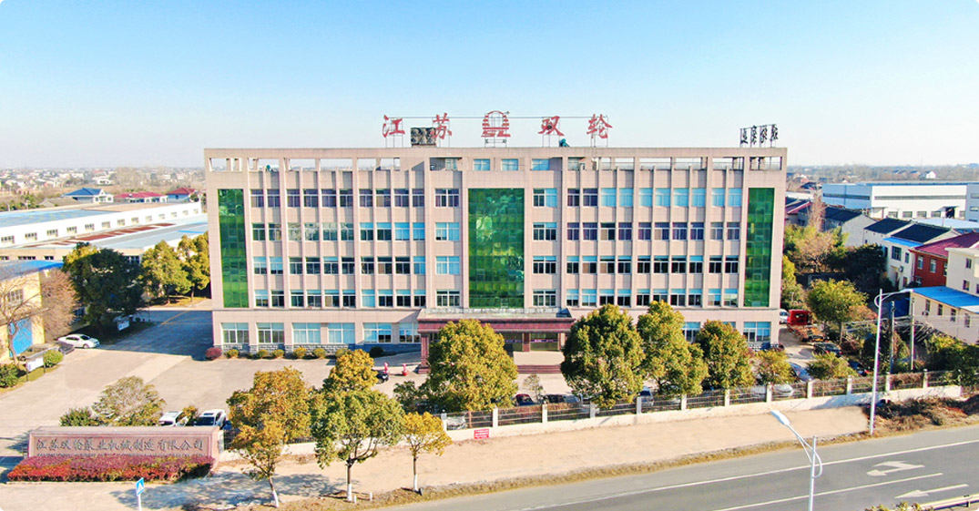
Jiangsu Double-wheel Pump Machinery Manufacting Co.,Ltd.
Jiangsu Double Wheel Pump Machinery Manufacturing Co., Ltd. is China Vertical Pipeline Centrifugal Liquid Pump Manufacturers and Wholesale Vertical Pipeline Centrifugal Liquid Pump Factory. The company is located in the scenic Yangtze River bank, Jiangyin Bridge, Beijing-Shanghai Expressway, Shanghai-Nanjing Expressway, Ningtong Expressway, Ningjingyan expressway running through the north and south, the traffic is very convenient, the geographical position is esteemed good. It is a production base specializing in non-sealed self-priming pumps, rain pumps, long-axis liquid pumps, chemical centrifugal pumps, positive displacement pumps and environmental protection equipment and mechanical equipment. The company has two production bases, covering an area of nearly 60,000 square meters, of which the eastern base covers an area of 33,000 square meters, the western base covers an area of 27,000 square meters, six modern production workshops, two installation workshops, a professional test workshop, a variety of mechanical processing equipment more than 160 sets, including a pump comprehensive performance test platform, Can test diameter 32-1200mm, motor power 1.1-1200KW, voltage 380V-10KV of various types of pumps, scientific research, development, manufacturing, processing, promotion, application of its own system. In the past two years, the company has closely followed the national industrial policy, made a big deal about environmental protection, and undertaken a large number of sewage treatment projects, which is unique in the environmental protection industry.
Certificate Of Honor


-
0

Be established in
-
0+

Professional personnel
-
0 million

Registered capital
-
0 ㎡

Plant area
After-Sales Service
Maintenance and Technical Support
Comprehensive lifecycle support for your vertical pipeline centrifugal pump installation.
Maintenance and Spare Parts
Keep your vertical pump operating reliably
-
Cartridge Mechanical Seal Kit: Complete cartridge seal assembly for quick replacement. Includes seal faces (SiC/Carbon), elastomers, and installation sleeve. Pre-assembled and tested.
-
Impeller Kit: Replacement enclosed impeller dynamically balanced. Includes key, locknut, and wear rings. Material as specified.
-
Motor Bearing Kit (Close-Coupled): Replacement motor bearings for close-coupled pumps. Includes drive end and non-drive end bearings.
-
Gasket Kit: Casing gasket, seal chamber gasket, and O-rings for complete pump reseal.
Professional Technical Support
Expert assistance for vertical pump applications
-
Pipe Support Analysis: We evaluate your piping system to ensure the pump flange loads are within acceptable limits. Recommendations for additional supports if needed.
-
NPSH Calculation: We calculate available NPSH for your piping configuration and recommend pump selection or piping changes to avoid cavitation.
-
VFD Sizing and Programming: We supply VFDs sized to your pump motor with pre-programmed parameters for PID control. Integration with building management systems (BMS) via BACnet or Modbus.
-
On-Site Seal Replacement Training: We train your maintenance staff on proper mechanical seal replacement procedures for vertical in-line pumps.

+86-0523- 84351 090 /+86-180 0142 8659


Welcome To
Jiangsu Double-Wheel Pump
Add 1: Hongguang Industrial Park, Jingjiang City, Jiangsu Province, China
Add 2: No.68, Xinyi Road, Industrial Park, Jingjiang City, Jiangsu Province, China
Contact
-
Tel:
+86-0523- 84351 090
+86-180 0142 8659 -
FAX:
+0523-8435 5588
- E-mail: