English
 русский
 عربى
عربى Indonesia
High Efficiency Fluid Technology Pump Wholesale


86–92% Hydraulic Efficiency
IE4 / IE5 Motor
Integrated VFD
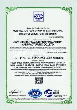
ISO 9001:2015
ISO 9906 Grade 1 Tested
High Efficiency Fluid Technology Pump
The HEF series delivers what decades of incremental pump design evolution could not — a genuine step-change in pumping system efficiency through the simultaneous optimisation of hydraulic geometry, motor efficiency class, and intelligent variable speed control. CFD-validated impeller profiles, Ra ≤ 3.2 µm precision passage finishing, IE4/IE5 motor integration, and SensorFlux VFD optimisation combine to deliver measured energy savings of 15–35% over the pumps your facility is running today. Certified by ISO 9906 Grade 1. Proven in the field. Quantifiable on your energy bill.
Product Introduction
Where Hydraulic Science Meets Industrial Reality — Maximum Efficiency, Minimum Waste.
A comprehensive technical overview of the HEF series High Efficiency Fluid Technology Pump — purpose-engineered for industrial, municipal, and commercial fluid handling applications where energy cost reduction, carbon footprint minimisation, and lifecycle operational economics are primary engineering objectives alongside reliability and performance.
The High Efficiency Fluid Technology Pump represents the convergence of four decades of hydraulic engineering advancement, modern computational fluid dynamics (CFD) modelling capability, precision manufacturing technology, and smart control systems integration into a single pump platform designed for one overriding purpose: to move fluid with the least possible consumption of energy. In an industrial world where pumping systems account for approximately 20–25% of total global industrial electricity consumption — and where individual large pump installations can consume millions of kilowatt-hours annually — even marginal improvements in hydraulic efficiency translate directly into substantial reductions in operating cost, carbon emissions, and grid energy demand. The HEF series was engineered specifically to make these improvements accessible to industries that have historically accepted mediocre pump efficiency as an unavoidable cost of operation.
The technical foundation of the HEF series is a family of CFD-optimised impeller and volute geometries developed in collaboration with the Fluid Technology Research Center of Jiangsu University. Unlike conventional pump hydraulic designs that use empirical scaling from historical performance data — accepting the efficiency losses that come with geometric compromises — the HEF impeller profiles are developed through an iterative CFD optimisation process that simultaneously minimises hydraulic losses in the impeller passages, the volute diffuser, and the tongue region where these two components interact. The result is a pump hydraulic design that achieves best efficiency point (BEP) hydraulic efficiencies of 86–92% — a 5–15 percentage point improvement over industry-average pumps of equivalent specific speed and flow range. Across a 10,000-hour operational year, this efficiency advantage compounds into energy savings that dwarf the initial pump purchase price difference.
A fundamental characteristic of the HEF series that distinguishes it from merely "efficient-at-one-point" catalogue pumps is its broad efficiency plateau. Conventional high-efficiency pumps are optimised for peak performance at a single duty point — and their efficiency falls sharply as operating conditions deviate from this point during real industrial operation. The HEF hydraulic design maintains efficiency within 3 percentage points of BEP across a flow range of 70–120% of best efficiency point flow. This wide efficiency plateau is critical in real industrial applications where system demand varies continuously — ensuring that energy savings are realised not just under ideal conditions but throughout the full operating cycle of batch processes, varying production rates, and seasonal demand changes.
The efficiency of the pump hydraulics alone, however, represents only part of the total system efficiency picture. The HEF series integrates a complete system efficiency engineering approach that addresses mechanical losses, motor efficiency, and variable speed control simultaneously. Mechanical losses are minimised through precision-ground bearing journals, optimised bearing selection (matched to actual radial and axial load profiles rather than being over-specified for safety margins), and a precision shaft alignment feature built into the bearing housing design. Motor efficiency is addressed through exclusive partnerships with IE4 and IE5 Super Premium Efficiency motor suppliers — motor efficiency at the rated operating point is matched to the pump operating point during the selection process to ensure the combined pump-motor system operates at maximum total efficiency, not just the pump or motor individually.
The third pillar of the HEF energy efficiency philosophy is variable speed control through integrated Variable Frequency Drive (VFD) technology. The Affinity Laws of centrifugal pumps state that power consumption varies with the cube of speed — reducing pump speed to 80% of rated speed reduces power consumption to approximately 51% of rated power. For any application where the required flow rate varies over time — which describes the overwhelming majority of real industrial pumping duties — VFD speed control delivers energy savings that fixed-speed pump operation with throttle valve control simply cannot match. The HEF series is designed from the outset for VFD operation, with motor windings specified for inverter duty, bearing insulation to prevent VFD-induced shaft current bearing damage, and SensorFlux speed-optimisation firmware in the integrated drive controller that continuously adjusts pump speed to maintain the system operating at the minimum energy point for any given demand condition.
Surface finish quality inside the pump hydraulic passages is a frequently overlooked contributor to pump efficiency — yet hydraulic surface roughness accounts for a measurable fraction of total hydraulic loss, particularly in smaller pumps where the passage dimensions amplify the relative roughness effect. The HEF series addresses this through a precision hydraulic passage finishing process that achieves internal surface roughness values of Ra ≤ 3.2 µm on all impeller and volute flow surfaces — compared to Ra 6.3–12.5 µm typical of standard sand-cast pump internals. This surface finishing step, combined with the CFD-optimised passage geometry, eliminates the local flow separation and turbulence generation that rough surfaces produce in boundary layer flow, contributing directly to the HEF's measured efficiency advantage.
The HEF series is available in three principal variants to serve different installation requirements: the HEF-H horizontal end-suction configuration for standard industrial process duties in ISO 2858 and ANSI B73.1 dimensional compliance; the HEF-V vertical inline configuration for space-constrained plant rooms, HVAC system integration, and piping systems where horizontal motor footprint is unavailable; and the HEF-S split-case configuration for the highest flow rates and multi-stage high-head applications where single-stage hydraulics cannot meet the combined flow and head requirement in a single pump unit. All three variants share the CFD-optimised hydraulic cores, IE4/IE5 motor integration, and smart control electronics that define the HEF series efficiency advantage.
Every HEF series pump is manufactured under ISO 9001:2015 quality management certification, tested on our precision pump test facility to ISO 9906 Grade 1 — the strictest factory acceptance test standard — and delivered with a certified performance test report that confirms the actual BEP efficiency, head-capacity curve, and power consumption at the specified duty point. For industrial energy auditing, procurement justification, and carbon accounting purposes, the ISO 9906 Grade 1 test report provides the certified efficiency data needed to calculate annual energy savings, payback period, and carbon reduction credits relative to the pump being replaced.
BEP hydraulic efficiency 86–92% — CFD-optimised by Jiangsu University FTR Center
Wide efficiency plateau — within 3% of BEP across 70–120% flow range
IE4 / IE5 Super Premium Efficiency motor — combined pump+motor efficiency maximised
Integrated VFD with SensorFlux speed-optimisation firmware
Ra ≤ 3.2 µm precision hydraulic passage surface finish
Three variants: HEF-H horizontal / HEF-V vertical inline / HEF-S split-case
ISO 2858 / ANSI B73.1 dimensional compliance — direct drop-in replacement
ISO 9906 Grade 1 factory acceptance test — certified efficiency documentation
Technical Data
Technical Specifications
Full performance, hydraulic, and construction parameters across the HEF series High Efficiency Fluid Technology Pump — covering all three variants: HEF-H horizontal end-suction, HEF-V vertical inline, and HEF-S split-case.
| Parameter | Specification |
|---|---|
Flow Rate Range | 5 m³/h – 8,000 m³/h |
Total Head Range | 5 m – 200 m (multi-stage HEF-S) |
Inlet / Outlet Diameter | DN 25 mm – DN 800 mm |
Motor Power Range | 0.75 kW – 3,000 kW |
Supply Voltage | 220 V / 380 V / 6 kV / 10 kV (50 Hz / 60 Hz) |
Rated Speed | 960 – 3,000 rpm (VFD range: 20–100% rated) |
Peak BEP Hydraulic Efficiency | 86% – 92% (flow / specific speed dependent) |
Efficiency Plateau Range | Within 3% of BEP from 70% to 120% of BEP flow |
Motor Efficiency Class | IE4 Super Premium (standard); IE5 Ultra Premium (option) |
Integrated VFD | SensorFlux VFD — standard for all HEF series units |
Surface Finish (Wetted) | Ra ≤ 3.2 µm impeller and volute flow surfaces |
Wetted Material Options | SS304, SS316L, Duplex 2205, Cast Iron, Bronze |
Shaft Seal Options | Single mechanical seal · Double seal · Mag-drive (sealless) |
Operating Temperature | −20 °C to +180 °C (material-dependent) |
Max Working Pressure | Up to 2.5 MPa (PN25); PN40 on request |
Dimensional Standard | ISO 2858 (HEF-H) / ANSI B73.1 (HEF-H) / EN 733 (HEF-V) |
Control Interface | Modbus TCP/RTU · PROFIBUS · BACnet · EtherNet/IP |
Explosion-Proof Option | Ex d IIB T4 / Ex d IIC T4 (ATEX / IECEx) |
Test and Design Standards | ISO 9906 Grade 1 · ISO 9001:2015 · CE · EU ErP 2015/1188 |
Energy Regulation Compliance | EU Ecodesign Reg. 547/2012 · GB 19762 (China) · MEPS |
Why Choose HEF
Core Advantages
Eight engineering and economic advantages that make the HEF series the most energy-efficient, most intelligently controlled, and most economically justified pump upgrade in industrial, municipal, and commercial fluid handling today.
CFD-Validated 86–92% Hydraulic Efficiency
Every HEF impeller and volute geometry is developed through full-domain CFD simulation — modelling velocity vectors, pressure gradients, turbulence kinetic energy, and wall shear stress across the entire flow path from pump inlet to discharge flange. The optimisation process simultaneously minimises all major hydraulic loss components: incidence loss at impeller blade leading edges, internal recirculation loss at part-load, disc friction loss, and volute diffusion loss. The result is a certified BEP efficiency that is independently verified by ISO 9906 Grade 1 factory testing.
Wide Efficiency Plateau — Real-World Energy Savings
Unlike pumps with sharp efficiency peaks that only deliver their rated efficiency under textbook ideal conditions, the HEF series maintains efficiency within 3 percentage points of BEP across a flow range of 70–120% of BEP. In industrial plants where flow demand varies continuously with production rate, batch scheduling, and seasonal demand cycles, this wide plateau ensures that energy savings are realised throughout the actual operating cycle — not just at the single design point used in procurement specifications.
IE4 / IE5 Motor — Total System Efficiency
A high-efficiency pump paired with a standard IE2 or IE3 motor delivers only partial system efficiency gains. The HEF series pairs its optimised hydraulics exclusively with IE4 Super Premium Efficiency and IE5 Ultra Premium Efficiency motors — the two highest internationally recognised motor efficiency classes. The pump-motor operating point is matched during selection to ensure both components operate at their highest efficiency simultaneously, maximising combined pump-motor system efficiency rather than optimising each in isolation.
SensorFlux VFD — Continuous Speed Optimisation
The integrated SensorFlux VFD controller goes beyond simple fixed-speed-setpoint control. Its proprietary algorithm continuously monitors system pressure, flow, and motor power consumption and adjusts pump speed in real time to maintain the minimum energy point for any given demand condition — automatically. Unlike standard VFD setups that require manual optimisation of speed setpoints, SensorFlux self-tunes its speed algorithm as system conditions change over time, delivering optimal efficiency throughout the full lifecycle of the installation.
Ra ≤ 3.2 µm Precision Surface Finish
Hydraulic surface roughness is a direct source of energy loss through increased wall friction and premature boundary layer transition in pump flow passages. The HEF precision finishing process achieves internal surface roughness of Ra ≤ 3.2 µm on all flow-wetted surfaces — three to four times smoother than standard sand-cast pump internals. In smaller pump sizes where the passage dimensions make relative roughness effects most significant, this surface finishing step contributes a measurable 1–3 percentage point improvement in hydraulic efficiency relative to unfinished castings of identical geometric form.
Quantifiable ROI — Typically 2–4 Year Payback
Every HEF project quote includes a formal Energy Savings Calculation (ESC) that converts the efficiency advantage of the HEF over the existing installed pump into annual kWh savings, annual monetary savings (at the customer's local electricity tariff), and a payback period for the investment differential. For large continuously running pumps in process industries, payback periods of 2–4 years are typical — with 15–25 years of net energy savings thereafter. The ESC provides the financial justification documentation needed for capital expenditure approval within your organisation.
EU Ecodesign and Global MEPS Compliance
The HEF series is fully compliant with EU Ecodesign Regulation 547/2012 (water pumps), EU ErP Directive 2015/1188 (circulation pumps), China GB 19762 energy efficiency standards, and applicable Minimum Energy Performance Standards (MEPS) in Australia, Canada, and other regulated markets. For industrial facilities subject to energy efficiency auditing, regulatory reporting, or sustainability certification (ISO 50001 Energy Management), HEF compliance documentation provides the verified performance data required by these frameworks.
ISO 2858 / ANSI B73.1 Drop-In Replacement
The HEF-H horizontal variant is dimensionally compliant with ISO 2858 and ANSI B73.1 standards — meaning it can replace any existing ISO or ANSI process pump without modifying pipe connections, foundation bolt patterns, or motor adapters. This eliminates the civil and mechanical modification costs that typically inflate pump replacement projects, reducing the total investment required and shortening the payback calculation. The HEF efficiency improvement is delivered as a bolt-in upgrade with zero infrastructure cost.
Use Cases
Primary Applications
The HEF series High Efficiency Fluid Technology Pump delivers maximum economic and environmental value in any application where pumps run for significant hours per year and where energy cost is a meaningful fraction of total operational expenditure — which describes the majority of industrial, municipal, and commercial pumping duties worldwide.
Municipal Water Supply and Distribution
Water treatment plant raw water intake, filtered water transfer, and pressurised distribution network booster stations are among the highest-energy-consumption pumping applications in any city's infrastructure. HEF-S split-case and HEF-H horizontal units operating at 86–92% hydraulic efficiency with IE4/IE5 motors and SensorFlux VFD pressure control deliver measurable reductions in the water utility's largest single operational expense — pumping energy — while simultaneously improving pressure stability and reducing pipe leakage driven by pressure transients from fixed-speed pump cycling.
HVAC Chilled Water and Heating Circulation
Building services chilled water loops, district heating networks, and large HVAC primary and secondary circulation systems run for 4,000–8,000 hours per year with continuously varying flow demand driven by occupancy, weather, and time-of-day load cycles. HEF-V vertical inline units with SensorFlux ΔP-constant pressure control and IE4 motor deliver BACnet and Modbus building management system integration, automatic balancing of circuit pressures, and measured energy savings of 20–40% over fixed-speed pumps with motorised control valve balancing systems.
Industrial Process Cooling Water
Cooling water circulation for compressors, heat exchangers, injection moulding machines, and industrial reactors typically runs continuously at near-design flow with periodic load-driven flow variations. HEF-H and HEF-S units replace standard cast iron centrifugal pumps in ISO 2858 and ANSI B73.1 cooling water duty, delivering 5–15 percentage point efficiency improvements that — in a large manufacturing plant where total cooling water pump power exceeds 500 kW — translate into annual energy savings exceeding 500,000 kWh per year.
Refinery and Petrochemical Utility Services
Refinery utility services — demineralised water supply, boiler feed water, cooling water make-up, firewater jockey pressure maintenance, and condensate return — involve large numbers of continuously running pumps whose aggregate energy consumption is a significant fraction of total plant utility cost. HEF API 610 OH2 compliant units deliver industry-standard construction and documentation compliance alongside the HEF series efficiency advantages — providing both the procurement specification compliance that refinery engineers require and the energy performance improvements that plant energy managers demand.
Agricultural and Irrigation Systems
Large-scale agricultural irrigation pump stations drawing from rivers, canals, or groundwater — operating for 1,500–3,000 hours per growing season — represent one of the highest-energy-consumption applications in the agricultural sector. HEF-S split-case and HEF-H units reduce irrigation energy costs that can represent 30–50% of total crop production cost in energy-intensive irrigated agriculture. VFD speed control provides precise flow management for different crop water requirements and soil moisture conditions without throttle valve energy waste.
Power Plant Auxiliary Systems
Power plant auxiliary pumping systems — circulating water, service water, condensate extraction, feedwater, and auxiliary cooling — run continuously and represent a significant parasitic load on the plant's net electrical output. A 1% improvement in pump efficiency on a 1 MW pump running continuously reduces parasitic load by 10 kW — worth approximately 87,600 kWh and considerable cost annually. HEF units replace existing auxiliary pumps as part of plant efficiency improvement programmes, contributing to improved net station heat rate and reduced carbon intensity per unit of generation.
Wastewater Treatment Plant Utilities
Wastewater treatment plant utilities — effluent recirculation, aeration tank mixed liquor return, UV disinfection feed, filtrate recirculation, and treated effluent discharge pumping — involve large numbers of medium-sized centrifugal pumps running for 6,000–8,000 hours per year. Plant energy benchmarking surveys consistently identify pump energy as the largest single controllable element of plant operating cost. HEF series replacements deliver both the energy savings and the SCADA-compatible monitoring data that modern WWTP energy management programmes require.
Data Centres and High-Tech Facilities
Data centre cooling water circulation — server room chilled water loops, adiabatic free-cooling circuits, and precision air conditioning chilled water distribution — demands ultra-reliable, highly efficient pumping that contributes to minimum Power Usage Effectiveness (PUE) ratios. HEF-V vertical inline units with N+1 redundancy, IE5 motors, BACnet building management integration, and remote monitoring provide the reliability and efficiency levels required by Tier III and Tier IV data centre specifications, contributing to both LEED certification points and cloud provider sustainability reporting metrics.
Head-to-Head
Performance Comparison
A detailed, parameter-by-parameter comparison of the HEF High Efficiency Fluid Technology Pump against standard efficiency industrial centrifugal pumps and basic high-efficiency pumps without integrated VFD or IE4/IE5 motors — across every dimension that determines real-world energy performance and total cost of ownership.
| Feature / Criteria | HEF High Efficiency Pump | Standard Efficiency Pump (IE2) | High-Eff. Pump (No VFD, IE3) |
|---|---|---|---|
| Peak Hydraulic Efficiency | 86–92% — CFD-optimised and certified | 72–80% — empirically scaled design | 80–86% — improved but not optimised |
| Efficiency at 70% BEP Flow | Within 3% of BEP — wide plateau | 10–18% below BEP — sharp drop | 6–12% below BEP — moderate drop |
| Motor Efficiency Class | IE4 standard; IE5 optional | IE2 — 3–8% lower than IE4 at rated load | IE3 — 2–5% below IE4 at rated load |
| Variable Speed Drive | Integrated SensorFlux VFD — standard | None — fixed speed, throttle valve control | Optional add-on — not factory integrated |
| Speed Optimisation Algorithm | SensorFlux auto-tunes to minimum energy point | Not applicable — fixed speed only | Manual setpoint — no self-optimisation |
| Surface Finish (Flow Passages) | Ra ≤ 3.2 µm — precision finished | Ra 12.5–25 µm — as-cast sand surface | Ra 6.3–12.5 µm — partially improved |
| Factory Test Standard | ISO 9906 Grade 1 — tightest tolerance | ISO 9906 Grade 3 or no test data | ISO 9906 Grade 2 — wider tolerance |
| Energy Savings Calculation (ESC) | Formal ESC with ROI calculation — standard | Not provided | Informal estimate only — not certified |
| EU Ecodesign Compliance | Full Reg. 547/2012 and ErP compliance | Fails current EU minimum efficiency index | Marginal compliance — no efficiency margin |
| SCADA / BMS Integration | Modbus · PROFIBUS · BACnet — all native | None — no digital interface | Basic Modbus only via external panel |
Expert Tips
Usage Tips and Best Practices
Maximise the energy savings, operational efficiency, and service life of your HEF series High Efficiency Fluid Technology Pump with these recommendations from our hydraulic engineering and energy optimisation team.
1
Verify the System Curve Before Commissioning
The HEF pump is selected to operate at its highest efficiency at the system design duty point — but if the actual installed system curve differs from the design curve (due to pipe sizing changes, valve position errors, or fouled filter elements), the pump will operate away from its BEP and the anticipated energy savings will not be fully realised. At commissioning, measure actual suction and discharge pressure at rated motor speed and compare the resulting operating point to the design H-Q curve. If the operating point is significantly above or below the BEP flow, investigate the cause in the system (pipeline, valves, or design curve error) before concluding that the pump is underperforming. A correct system curve match is the prerequisite for achieving the certified HEF efficiency levels in the field.
2
Commission SensorFlux VFD with Correct Control Mode
The SensorFlux VFD supports three principal control modes: constant pressure (ΔP-constant) for distribution systems where system pressure at a remote point must be held constant regardless of flow; proportional pressure (ΔP-variable) for building HVAC systems where setpoint pressure scales with flow demand (most energy-efficient for variable-flow distribution); and constant flow for process duties requiring fixed volumetric throughput. Selecting the correct mode for your system architecture is the most important SensorFlux commissioning decision. An incorrect mode selection (e.g., constant pressure in an HVAC system that should use proportional pressure) can negate 30–50% of the potential VFD energy saving. Our commissioning engineers confirm correct mode selection during first-start supervision.
3
Establish and Track the Energy Performance Baseline
To quantify and report the actual energy savings achieved by the HEF installation, establish a documented energy baseline before the existing pump is replaced: record motor power consumption (kW), flow rate (m³/h), and pump pressure (m) over a representative operating period — at minimum one full production cycle or one full diurnal flow pattern. After HEF commissioning, record the same parameters under the same system conditions. The difference in specific energy consumption (kWh/m³) is your verified energy saving metric — suitable for internal reporting, ISO 50001 energy management records, carbon accounting, and ESG disclosure frameworks. The SensorFlux VFD data logger records all operating parameters continuously, providing an automatically generated energy performance record without manual data collection.
4
Avoid Operating at Minimum Flow for Extended Periods
All centrifugal pumps — including high-efficiency designs — generate internal recirculation at flow rates below approximately 60–70% of BEP flow, creating excessive radial load on the shaft, hydraulic pulsation, and elevated fluid temperature in the pump casing. For applications with genuine minimum-flow operating periods (pump-to-tank filling at the end of a batch cycle, or standby pressure maintenance), install a minimum flow bypass line returning flow to the suction vessel — sized for at least 25% of BEP flow. The SensorFlux VFD can automatically open a motorised bypass valve when flow falls below the minimum threshold, protecting the pump and maintaining efficiency without operator intervention.
5
Bearing Lubrication — Precision, Not Volume
The HEF series uses precision-ground bearing journals and selected bearing clearances that optimise mechanical efficiency at the specified operating conditions. Using incorrect lubricant grade or quantity in these precision bearings degrades efficiency and accelerates wear. Use only the lubricant grade specified in the HEF O&M manual (typically ISO VG 46 or ISO VG 68 circulating oil, or NLGI 2 lithium-complex grease depending on bearing type). Grease-lubricated bearings should be re-greased at the specified interval using a measured grease gun (not a bulk pump) — over-greasing causes churning losses that raise bearing temperature and reduce bearing life, directly increasing mechanical losses in an otherwise highly efficient pump.
6
Monitor Specific Energy — Not Just Flow and Pressure
Traditional pump monitoring measures flow and pressure separately and relies on manual comparison to the H-Q curve to detect performance degradation. For the HEF series, configure the SensorFlux data logging to continuously calculate and record specific energy consumption (kWh/m³) — the ratio of power consumed to volume delivered. This single metric captures all sources of performance degradation simultaneously: hydraulic efficiency loss from impeller erosion or scale deposition, mechanical efficiency loss from bearing wear, and motor efficiency changes from winding deterioration or VFD fault conditions. A rising specific energy trend that is not explained by system condition changes indicates a developing pump problem that warrants investigation — catching it early prevents both energy waste and unplanned failure.
7
Impeller Clearance Adjustment for Wear Compensation
The HEF series impeller wear ring clearance is a critical efficiency parameter — as the wear ring clearance increases through normal mechanical wear, internal recirculation flow from the discharge side back to the impeller eye increases, reducing both flow and efficiency. The HEF bearing housing includes an axial adjustment mechanism for the impeller position, allowing the impeller-to-casing clearance to be restored to the factory specification after wear without replacing the impeller or casing. Check and adjust impeller clearance at each annual maintenance — a worn clearance that has doubled from the factory setting causes approximately 3–5% efficiency loss that is fully recoverable by adjustment. Instructions for clearance measurement and adjustment are included in the HEF O&M manual.
8
Use the HEF for System Optimisation, Not Just Pump Replacement
The greatest energy saving opportunity is often not in the pump itself but in the system it serves. When commissioning a HEF replacement pump, use the opportunity to audit the entire piping system for efficiency-robbing features: throttled control valves that dissipate energy which should never have been generated; oversized pipes with excessive flow velocities; unnecessary elevation changes; partially blocked strainers adding suction resistance; and parallel pump installations where system flow has declined since original design, allowing one pump to be shut down entirely. A SensorFlux VFD-equipped HEF combined with system optimisation frequently delivers 40–50% total system energy savings — far exceeding the 15–20% that pump efficiency improvement alone achieves.
FAQ
Frequently Asked Questions
Clear, engineering-level answers to the questions most frequently asked by plant energy managers, procurement engineers, and sustainability teams about the HEF series High Efficiency Fluid Technology Pump — covering efficiency claims, payback calculation, regulatory compliance, and technical specifications.
How is the 86–92% hydraulic efficiency figure verified — is it a theoretical calculation or a measured value?
The HEF hydraulic efficiency figure is a measured, certified value from the factory acceptance test — not a theoretical prediction. Every HEF pump is tested on our precision pump test facility per ISO 9906 Grade 1, the most stringent internationally recognised pump performance test standard. The test measures actual head, flow, and shaft power at a minimum of five operating points, calculates hydraulic efficiency at each point, and identifies the BEP efficiency from the measured data. The ISO 9906 Grade 1 certified factory test report, signed by our QC manager, is delivered with every pump and provides the legally verifiable efficiency data. Grade 1 acceptance tolerances are ±4.5% on head and ±8% on efficiency — substantially tighter than the Grade 2 or Grade 3 standards used by many pump manufacturers. The 86–92% range reflects the natural variation of BEP efficiency with pump size and specific speed — smaller pumps (lower flow, higher head) achieve the lower end; larger pumps achieve the upper end.
How do you calculate the energy savings and payback period for an HEF replacement project?
We provide a formal Energy Savings Calculation (ESC) with every HEF quotation. The methodology is: (1) Establish existing pump efficiency from its test data or nameplate, or from a site efficiency measurement if data is unavailable; (2) Determine HEF efficiency at the same duty point from our ISO 9906 Grade 1 test data; (3) Calculate the power saving = flow rate (m³/s) × head (m) × fluid density × gravity × (1/existing efficiency − 1/HEF efficiency); (4) Multiply by annual operating hours to get annual kWh saving; (5) Multiply by electricity unit cost to get annual monetary saving; (6) Divide the investment differential (HEF price minus existing pump replacement price) by annual monetary saving to get payback period. The ESC also includes the VFD energy saving calculated from the Affinity Law for the observed system load variation profile. For complex multi-pump stations with variable load profiles, we build a weighted average efficiency model across the actual operating hours distribution.
What is the difference between IE4 and IE5 motor efficiency classes?
IE efficiency classes for electric motors are defined in IEC 60034-30-1. IE4 (Super Premium Efficiency) is approximately 1–2% more efficient than IE3 (Premium Efficiency) at rated load — a difference that represents significant energy savings at large motor powers. IE5 (Ultra Premium Efficiency) is approximately 0.5–1% more efficient than IE4, representing the current engineering frontier for induction and synchronous reluctance motor efficiency. For a 100 kW motor operating 8,000 hours per year, the difference between IE3 and IE5 is approximately 8,000–12,000 kWh annually — a meaningful contribution to the total system efficiency advantage. IE4 is the HEF standard specification; IE5 is offered as an option for the largest, most continuously running pumps where the marginal cost of IE5 over IE4 is justifiable by the additional energy savings. We recommend IE5 for motors above 75 kW in applications running more than 6,000 hours per year.
Can the HEF pump replace my existing ISO 2858 or ANSI B73.1 pump without any piping modification?
Yes — the HEF-H horizontal variant is fully dimensionally compliant with ISO 2858 (metric) and ANSI B73.1 (inch) pump interface standards. This means all pipe connection centrelines, flange face positions, foundation bolt hole patterns, and motor adapter (IEC or NEMA frame) dimensions are identical to the original ISO or ANSI pump being replaced — allowing a direct bolt-in swap with zero piping, foundation, or motor adapter modification. To confirm direct replaceability for your specific existing pump, provide us with the make, model, and size designation of the pump you wish to replace (e.g., "50-32-200" for ISO format or "2×3-10" for ANSI format), and we will issue a dimensional comparison drawing before you commit to purchase. The HEF-V vertical inline variant is dimensionally compliant with EN 733 (formerly DIN 24255) for direct replacement of standard vertical inline pumps in HVAC and building services applications.
What SCADA and building management system protocols does the SensorFlux VFD support?
The SensorFlux VFD controller supports Modbus RTU (RS-485), Modbus TCP/IP (Ethernet), PROFIBUS-DP, BACnet MS/TP, BACnet IP, and EtherNet/IP as standard communication protocols — covering virtually all SCADA, DCS, PLC, and Building Management System (BMS) platforms in industrial and commercial use. BACnet support is particularly important for HVAC and building services applications where Johnson Controls Metasys, Siemens Desigo, Honeywell EBI, and Schneider EcoStruxure are the dominant BMS platforms. For industrial SCADA environments, Modbus and PROFIBUS cover Siemens S7/TIA Portal, Allen-Bradley ControlLogix, and ABB 800xA installations. Full register maps, GSD files, BACnet device profiles, and EDS files are provided in the SensorFlux documentation package for SCADA and BMS integration engineers.
Does the HEF series comply with EU Ecodesign regulations for pumps?
Yes, fully. The HEF series complies with EU Commission Regulation (EU) No. 547/2012 — the Ecodesign implementing measure for water pumps — which sets Minimum Efficiency Index (MEI) requirements that have progressively tightened since 2013. HEF pumps achieve MEI ≥ 0.70, substantially above the current mandatory minimum of MEI ≥ 0.40. The HEF also complies with EU Commission Regulation (EU) 2015/1188 (ErP Directive for circulation pumps — Energy Efficiency Index EEI). For the motor component, IE4 motors comply with the Phase 3 requirements of EU Motor Regulation (EU) 2019/1781 effective July 2023. CE marking for both pump and motor is provided with each unit, along with the EU Declaration of Conformity referencing all applicable directives and regulations. For projects requiring export to the UK post-Brexit, UKCA marking is also available.
Can the HEF be used for fluids other than clean water — chemicals, oil, or hot liquids?
Yes. The HEF series is not limited to clean water service. Wetted material options include SS304, SS316L, Duplex 2205, cast iron, and bronze — covering a broad range of chemical, industrial fluid, and hot liquid applications. The HEF precision-finished Ra ≤ 3.2 µm surface finish is equally beneficial for chemical process fluids and heat transfer liquids as for water service — the efficiency advantage from reduced hydraulic roughness applies to any Newtonian liquid. For highly corrosive or aggressive chemical fluids, the HEF-H horizontal variant is available with double mechanical seals or mag-drive sealless configuration, extending its chemical compatibility to the same range as the CRP chemical process pump series. Provide your fluid name, specific gravity, viscosity, temperature, and pH and we will confirm material compatibility and any hydraulic correction for non-water fluid properties.
How does the HEF contribute to ISO 50001 energy management and carbon reporting?
The HEF series directly supports ISO 50001 Energy Management System (EnMS) implementation in three ways. First, the SensorFlux VFD data logger provides continuous, automatically recorded energy consumption data (kWh), flow rate (m³), and specific energy (kWh/m³) for every operating period — eliminating the manual data collection burden for energy significant areas (EnSA) that ISO 50001 requires. Second, the ISO 9906 Grade 1 factory test report provides the certified baseline efficiency data for EnMS energy performance indicator (EnPI) calculation. Third, the formal Energy Savings Calculation (ESC) provided with each HEF quotation gives the projected annual kWh reduction and CO₂-equivalent emission reduction data in the format required by ISO 50001 improvement action documentation, GHG Protocol Scope 2 reporting, and corporate sustainability reporting frameworks (GRI, SASB, TCFD).
Are government energy efficiency incentives or subsidies available for HEF installations?
Energy efficiency incentive programmes vary by country and region, but many jurisdictions offer financial support for industrial pump efficiency upgrades. Common programmes include: Enhanced Capital Allowance (ECA) schemes in the UK for energy-saving plant and machinery; industrial energy efficiency rebates from electricity utilities in many countries (typically €20–80 per MWh of verified annual saving); EU Cohesion Fund grants for energy efficiency projects in eligible regions; China's industrial energy efficiency subsidy programmes under the "Made in China 2025" industrial policy; and tax credit schemes in various Middle Eastern and Southeast Asian markets targeting industrial energy reduction. The HEF ISO 9906 Grade 1 test certificate and formal Energy Savings Calculation documentation provide the verified efficiency improvement evidence required by virtually all incentive programme application processes. We assist customers with incentive programme identification and documentation preparation as part of our project support service.
What is the typical lead time and minimum order quantity?
Minimum order quantity is 1 unit. Standard HEF-H and HEF-V units in SS316L or cast iron with IE4 motor and SensorFlux VFD in common power ratings (0.75–90 kW) ship within 20–30 business days. Medium-large units (90–500 kW) with IE4 motor require 30–45 business days. HEF-S split-case units and configurations above 500 kW require 45–65 business days. IE5 motor configurations and Duplex 2205 material variants add 10–15 business days. ATEX-certified units add 10–15 business days for certified motor sourcing. For urgent replacement projects (failed pump at running plant, production stoppage risk), contact our urgent supply team — we maintain a stock of standard-size HEF-H casings, impellers, and assembled rotating units in common ISO sizes for accelerated dispatch.
Company
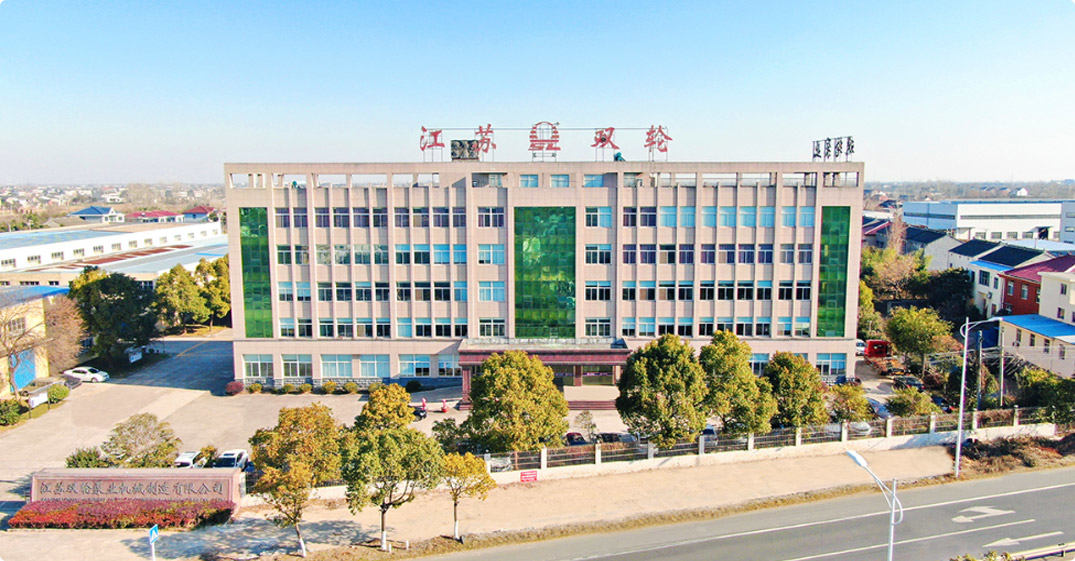
Jiangsu Double-wheel Pump Machinery Manufacting Co.,Ltd.
Jiangsu Double Wheel Pump Machinery Manufacturing Co., Ltd. is China High Efficiency Fluid Technology Pump Manufacturers and Wholesale High Efficiency Fluid Technology Pump Factory. The company is located in the scenic Yangtze River bank, Jiangyin Bridge, Beijing-Shanghai Expressway, Shanghai-Nanjing Expressway, Ningtong Expressway, Ningjingyan expressway running through the north and south, the traffic is very convenient, the geographical position is esteemed good. It is a production base specializing in non-sealed self-priming pumps, rain pumps, long-axis liquid pumps, chemical centrifugal pumps, positive displacement pumps and environmental protection equipment and mechanical equipment. The company has two production bases, covering an area of nearly 60,000 square meters, of which the eastern base covers an area of 33,000 square meters, the western base covers an area of 27,000 square meters, six modern production workshops, two installation workshops, a professional test workshop, a variety of mechanical processing equipment more than 160 sets, including a pump comprehensive performance test platform, Can test diameter 32-1200mm, motor power 1.1-1200KW, voltage 380V-10KV of various types of pumps, scientific research, development, manufacturing, processing, promotion, application of its own system. In the past two years, the company has closely followed the national industrial policy, made a big deal about environmental protection, and undertaken a large number of sewage treatment projects, which is unique in the environmental protection industry.
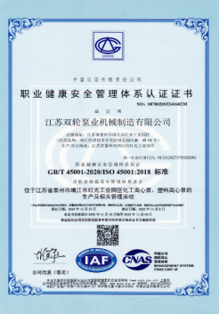
Certificate Of Honor


-
0

Be established in
-
0+

Professional personnel
-
0 million

Registered capital
-
0 ㎡

Plant area
After-Sales Service
Maintenance and Technical Support
Comprehensive lifecycle support for HEF installations — from pre-purchase energy savings analysis and ISO 9906 Grade 1 factory testing through commissioning, ongoing energy performance monitoring, predictive maintenance programmes, and long-term system optimisation advisory services across the full 20+ year pump service life.
Maintenance and Spare Parts
Sustaining certified efficiency performance across the full service life
- Annual Efficiency Verification Service: We offer an annual performance verification visit for HEF installations, during which our engineers measure actual pump head, flow, and motor power consumption at the operating duty point, calculate the current specific energy (kWh/m³), and compare it to the original ISO 9906 Grade 1 baseline from the factory test report. Any efficiency degradation is diagnosed and attributed to its root cause — impeller wear, wear ring clearance increase, scale deposition on flow surfaces, or bearing mechanical loss increase — and a remediation recommendation is provided. This service provides the documented efficiency data required for ISO 50001 performance indicator tracking.
- Precision Replacement Impeller Supply: Replacement impellers for the HEF series are manufactured to the same precision hydraulic geometry as the original — CFD-designed, precision-cast, and finished to Ra ≤ 3.2 µm internal surface roughness with dynamic balance to ISO 1940 G2.5. A replacement impeller that restores the original hydraulic geometry and surface finish restores the original efficiency performance. We do not supply generic "close enough" replacement impellers — every replacement part is a genuine HEF-specification component manufactured to the original engineering standards.
- Wear Ring Clearance Restoration Kit: The HEF impeller wear ring clearance is the primary mechanical variable controlling internal recirculation loss and hydraulic efficiency. We supply a wear ring clearance restoration kit containing new impeller wear rings, casing wear rings (where applicable), and an impeller setting procedure card with the factory clearance specification. Restoring worn clearances to factory specification recovers the 3–5% efficiency loss that typical clearance wear causes — a cost-effective efficiency restoration that extends the interval before a full impeller replacement is required.
- SensorFlux VFD Preventive Maintenance: The SensorFlux VFD contains cooling fans and DC bus capacitors that require periodic inspection and replacement to maintain VFD reliability. We supply a VFD preventive maintenance service at 5-year intervals, covering: cooling fan inspection and replacement, DC bus capacitor condition assessment, output filter inspection, firmware update, and full functional test of all control modes and communication protocols. Maintaining VFD health is critical to preserving the energy savings that make the HEF system economically superior — a failed VFD reverting to fixed-speed operation eliminates the VFD efficiency contribution immediately.
- Long-Term Spare Parts Commitment: HEF series spare parts — impellers, wear rings, mechanical seals, bearing sets, shaft sleeves, and SensorFlux VFD modules — are guaranteed available for a minimum of 12 years from delivery date. For long-term service contracts, we offer consignment stock of critical spare parts held at our warehouse and dispatched same-day on receipt of purchase order, eliminating lead time risk in emergency situations. The HEF back-pull-out design allows any rotating assembly component to be replaced in under two hours with standard tools, minimising production interruption during maintenance events.
Professional Technical Support
Engineering expertise for energy optimisation at every project stage
- Pre-Purchase Energy Audit and Savings Analysis: For customers considering HEF pump replacements in multiple pumping duties across a facility, we offer a pre-purchase pump energy audit service. Our engineers review your existing installed pump data (make, model, rated duty, actual operating conditions, motor nameplate efficiency, and annual operating hours) and produce a priority-ranked list of replacement opportunities with individual Energy Savings Calculations (ESC), payback periods, and aggregate facility energy reduction potential. This audit provides the business case documentation for multi-pump capital expenditure approval.
- System Curve Analysis and Optimisation: The HEF pump efficiency advantage is only fully realised when the pump operates at or near its BEP on the actual system curve. Our engineers analyse your pipeline system — including static head, pipe friction at various flow rates, valve pressure drops, and elevation changes — to construct the accurate system curve and confirm that the HEF selection operates within the efficiency plateau (70–120% BEP flow) under all anticipated operating conditions. System modifications that would move the operating point closer to BEP are identified and quantified for their additional energy saving potential.
- SensorFlux Commissioning and Optimisation: Our controls engineers provide factory-trained SensorFlux VFD commissioning support — confirming correct control mode selection (ΔP-constant, ΔP-variable, or constant flow), calibrating pressure transducer inputs, setting minimum speed limits (to prevent motor heating at minimum flow), configuring SCADA communications, and verifying the SensorFlux self-optimisation algorithm is achieving minimum energy operating points. Post-commissioning, we review the first 30 days of SensorFlux operational data and provide a tuning report with any recommended parameter adjustments to further improve energy performance.
- ISO 50001 Energy Management Documentation Support: For customers implementing ISO 50001 Energy Management Systems, our team provides the complete pump-related documentation package: ISO 9906 Grade 1 factory test report as EnPI baseline data, Energy Savings Calculation for action plan documentation, SensorFlux energy logging data format specification for EnMS data collection, and annual efficiency verification report for continual improvement evidence. We also provide a technical briefing for your ISO 50001 internal audit team on pump energy performance indicators and the methodology for calculating pump system energy significant area (EnSA) boundaries and baselines.
- Long-Term System Efficiency Advisory: Over the multi-decade service life of an HEF pump installation, system conditions change — production rates shift, pipe scales develop, system expansions add parallel branches, and control system upgrades present new optimisation opportunities. Our long-term advisory service provides periodic (typically triennial) system efficiency reviews, identifying opportunities to further improve specific energy consumption through SensorFlux parameter updates, system modifications, additional pump replacements, or energy recovery turbine installations on pressure-reducing stations. This ongoing advisory relationship ensures that the HEF installation continues to deliver maximum energy performance throughout its full operational life.

+86-0523- 84351 090 /+86-180 0142 8659


Welcome To
Jiangsu Double-Wheel Pump
Add 1: Hongguang Industrial Park, Jingjiang City, Jiangsu Province, China
Add 2: No.68, Xinyi Road, Industrial Park, Jingjiang City, Jiangsu Province, China
Contact
-
Tel:
+86-0523- 84351 090
+86-180 0142 8659 -
FAX:
+0523-8435 5588
- E-mail: