English
 русский
 عربى
عربى Indonesia
Large Flow Rate Rain Water Pump Wholesale


Ultra-High Flow
Instant Auto-Start
ISO 9001:2015
Flood Control Proven
GSM/4G Remote Control
Large Flow Rate Rain Water Pump
When the storm hits, the RWP series is already running. Permanently submerged, instantly responsive, and engineered for flow rates that no urban flood event can overwhelm — from compact municipal drainage stations handling thousands of cubic meters per hour to major flood control infrastructure moving entire river flows. Three configurations. Any depth. Any climate. Any storm.
Product Introduction
Maximum Flow. Instant Response. Built for the Worst Storms the World Can Deliver.
A comprehensive technical overview of the RWP series Large Flow Rate Rain Water Pump — purpose-engineered for urban flood control, storm drainage infrastructure, municipal rainwater management, and large-scale surface water abstraction where massive flow capacity and absolute operational reliability are non-negotiable.
The Large Flow Rate Rain Water Pump addresses the most time-critical challenge in municipal and industrial hydraulic infrastructure: moving enormous volumes of storm runoff, rainwater, and surface water rapidly enough to prevent urban flooding, protect critical infrastructure, and maintain safe drainage under the most extreme precipitation events. As climate change drives increasingly frequent and intense rainfall events in urban centers worldwide, the engineering requirements for rainwater pumping systems have escalated dramatically. A pump that was adequate for a 1-in-10-year storm event a decade ago may be critically undersized for the 1-in-50-year events that are now occurring with alarming regularity. The RWP series is designed from first principles for this new reality — delivering peak flow rates that set a new standard for what a rainwater pump can achieve.
The RWP series is available in three principal configurations optimized for different rainwater management scenarios. The RWP-A axial flow (propeller) pump configuration delivers ultra-high flow rates at low to moderate head — the definitive choice for flat-terrain drainage systems, canal lift stations, tidal barrier pumping, and river-to-sea drainage where large volumes must be moved with minimal elevation change. Flow rates in RWP-A units exceed 50,000 m³/h per unit in the largest configurations, making single-unit installations practical for major urban flood control pump stations. The RWP-M mixed flow pump configuration offers a balanced head-flow envelope suited to medium-depth drainage basins, combined sewer overflow (CSO) management, and regional stormwater retention pond emptying. The RWP-C centrifugal volute pump configuration provides higher head capability for pump stations where significant elevation difference exists between the collection sump and the discharge point — such as pumping from below-grade highway underpasses, deep railway cuttings, or reclaimed low-lying urban land protected by dikes and flood barriers.
All three RWP configurations share a core design philosophy: maximum hydraulic passage area, minimum blockage risk. Rainwater is never clean water. Urban storm runoff carries leaves, branches, plastic debris, silt, sand, and occasional larger solid objects. A rainwater pump that blocks in a storm event is not merely inconvenient — it is potentially catastrophic. The RWP series addresses this through large-clearance impeller designs (minimum 80 mm free-passage diameter in the smallest units, scaling to 400 mm in large units), cast iron or stainless steel trash screens with generous bar spacing, and a volute casing geometry optimized to prevent debris accumulation at low-velocity dead zones. The semi-open and fully open impeller designs used in RWP-A and RWP-M configurations minimize the risk of fibrous or leafy debris wrapping around the impeller — the most common blockage mechanism in storm drainage pumps.
A defining feature of effective rainwater pump station design is start reliability from zero notice. A flood control pump may sit on standby for weeks or months between activation events, then be required to start at full rated capacity within seconds of a control signal during a storm emergency. The RWP series is designed explicitly for this duty profile. All RWP units are configured with the pump bowl permanently submerged below the minimum wet well level, eliminating any priming requirement. Motor starting systems are integrated with automatic control panels that monitor wet well level through ultrasonic or pressure transducer sensors and activate pumps in a predetermined sequence as water level rises — with no operator intervention required. Test-run automation sequences exercise each pump unit on a weekly schedule to verify starting reliability and detect any mechanical deterioration between storm events, long before the next real emergency occurs.
Construction materials are selected for the demanding environment of permanent outdoor installation in wet sumps exposed to combined rainfall runoff containing road salts, de-icing chemicals, urban pollutants, and variable pH from acidic rainfall. Standard RWP construction uses grade 250 close-grained cast iron for pump casings and impellers — providing excellent resistance to the mild corrosivity of rainwater while maintaining the stiffness and damping properties needed to minimize vibration transmission in large pump installations. For coastal installations where seawater intrusion and salt-spray exposure are concerns, SS316 wetted components are available. For severely corrosive industrial catchment areas where the runoff contains chemical plant effluents, Duplex 2205 stainless steel construction is offered. All external surfaces receive a two-coat epoxy-coal tar coating system (minimum 400 µm DFT) for long-term protection of buried or permanently wet external surfaces.
The electrical and control systems supplied with RWP pump stations are designed and built to IP65 minimum ingress protection rating, with motor winding insulation class F and protection class IP55 as standard — ensuring reliable operation in the high-humidity, water-splash environment of an active pump station during a storm event. Variable frequency drives (VFDs) are offered as standard equipment on units above 45 kW, providing soft-start capability to eliminate water hammer in long discharge mains, proportional speed control for level-following operation, and energy savings during partial-load operation between storm peaks. Each RWP pump station control panel includes a GSM/4G telemetry module for remote monitoring, alarm transmission, and manual override capability — allowing water authority operators to monitor and control the pump station from a central operations center without on-site attendance during a storm event.
Every RWP series pump is manufactured under ISO 9001:2015 quality management certification, tested on our high-capacity pump test facility before delivery, and documented with a certified factory performance test report per ISO 9906. For major municipal and infrastructure projects, we provide full project documentation packages including hydraulic design calculations, wet well design recommendation per ANSI/HI 9.8, electrical single-line diagrams, control philosophy documents, O&M manuals, and spare parts lists — supporting the full project engineering and handover process from concept to commissioning.
Three configurations: axial flow / mixed flow / centrifugal volute
Flow rates up to 50,000+ m³/h per single axial flow unit
Large-clearance impeller — 80 to 400 mm solids free-passage
Permanently submerged bowl — zero priming delay, instant start
Automatic level-sensing control panel with GSM/4G telemetry
VFD standard above 45 kW — soft start, energy saving, level-following
Epoxy-coal tar external coating — 400 µm DFT for buried/wet service
ISO 9001:2015 certified; ISO 9906 factory performance test
Technical Data
Technical Specifications
Full performance and construction parameters for the RWP series Large Flow Rate Rain Water Pump — across all three configurations: axial flow (RWP-A), mixed flow (RWP-M), and centrifugal volute (RWP-C).
| Parameter | Specification |
|---|---|
Flow Rate Range | 500 m³/h – 50,000+ m³/h (single unit) |
Total Head Range | 1 m – 30 m (configuration-dependent) |
Pump Configurations | RWP-A Axial Flow · RWP-M Mixed Flow · RWP-C Centrifugal Volute |
Impeller / Inlet Diameter | 300 mm – 3,000 mm |
Discharge Pipe Diameter | DN 200 mm – DN 2,400 mm |
Motor Power Range | 11 kW – 5,000 kW |
Supply Voltage | 380 V / 6 kV / 10 kV (50 Hz / 60 Hz) |
Motor Speed Range | 150 – 980 rpm (slow speed for large impellers) |
Solids Free-Passage | 80 mm – 400 mm (unit-size dependent) |
Wetted Material — Standard | Grade 250 Close-Grain Cast Iron |
Wetted Material — Options | SS316, Duplex 2205, Rubber-Lined Cast Iron |
External Coating | Epoxy-coal tar, 400 µm DFT minimum |
Operating Temperature | 0 °C to +60 °C |
Impeller Type | Axial propeller · Mixed flow · Semi-open centrifugal · Open centrifugal |
Motor Protection | IP55 standard · IP65 available · Class F insulation |
Speed Control | VFD standard ≥ 45 kW; DOL or star-delta below 45 kW |
Remote Monitoring | GSM / 4G / Ethernet telemetry; Modbus RTU/TCP; SCADA-ready |
Installation Type | Vertical sump · Dry pit · Submersible · Horizontal (RWP-C) |
Standards and Certs | ISO 9001:2015 · ISO 9906 · ANSI/HI 9.8 wet well design |
Why Choose RWP
Core Advantages
Eight engineering and operational advantages that make the RWP series the most reliable, highest-capacity, and most operationally resilient large flow rate rainwater pump for urban flood control and storm drainage infrastructure worldwide.
Ultra-High Flow in a Single Unit
The RWP-A axial flow configuration delivers over 50,000 m³/h through a single pump unit — the equivalent of draining an Olympic swimming pool every 5.4 seconds. This massive single-unit flow capacity reduces the number of parallel pumping units required in a flood control station, reducing civil structure size, electrical infrastructure cost, and the number of control and maintenance points in the installation.
Zero Priming — Instant Emergency Start
Every RWP pump is configured with the inlet permanently submerged below the minimum wet well operating level. There is no priming required, no foot valve to fail, and no delay between the control system issuing a start command and the pump delivering full rated flow. In a flood emergency where water levels are rising faster than drainage can cope, every second of priming delay translates directly to additional property damage and life safety risk. The RWP eliminates this risk entirely.
Anti-Blockage Large-Passage Design
Storm runoff is the most debris-laden fluid any pump is asked to handle. The RWP impeller passage geometry provides a minimum 80 mm free-passage diameter (scaling to 400 mm in large units), combined with large-radius inlet and discharge passage curvature that prevents debris accumulation at stagnation points. The propeller and mixed flow impeller designs used in RWP-A and RWP-M units minimize fibrous material wrapping — the single most common operational failure mode in storm drainage pumps worldwide.
Fully Automated — No Operator Required
The RWP control system monitors wet well water level continuously via dual-redundant ultrasonic sensors, starts and stops pumps in a pre-programmed sequence as level rises and falls, rotates the duty pump assignment to equalize running hours, transmits real-time status and alarm data via GSM/4G telemetry, and performs weekly automated test-run sequences — all without any operator being present. Water authority control rooms receive complete pump station data on their SCADA screens in real time, 24 hours a day.
VFD Level-Following Control
Variable frequency drives on RWP units above 45 kW allow the pump speed — and therefore flow rate — to be continuously varied in proportion to the wet well level. As water rises rapidly during a storm peak, pumps accelerate to maximum speed. As the storm passes and inflow drops, pump speed reduces proportionally, maintaining the wet well at the target level without hunting between full-on and full-off. VFD operation also eliminates the water hammer transients that repeated direct-on-line starts and stops produce in long discharge mains.
Three Configurations for Every Hydraulic Scenario
No single pump configuration is optimal for every rainwater management scenario. The RWP-A axial flow pump excels at ultra-high-flow, very-low-head drainage of flat catchments. The RWP-M mixed flow pump provides balanced performance for medium-head regional drainage. The RWP-C centrifugal volute pump delivers higher head for deep sumps, highway underpass drainage, and pumping against tidal or river back-pressure. Selecting the right configuration — not over-specifying on head — is the key to efficient rainwater pump station design, and the RWP family covers the full spectrum.
Dry Pit and Wet Pit Installation Flexibility
RWP pumps are available in both wet pit (vertical sump, motor above wet well) and dry pit (horizontal or vertical, pump and motor both in a dry vault adjacent to the wet well) installation configurations. Dry pit installation allows direct access to all pump mechanical components without entering a wet space — simplifying inspection, maintenance, and any emergency work during or immediately after a storm event when the wet pit may be at its highest level.
Long Service Life in Outdoor Wet Environments
The combination of close-grain cast iron pump casing construction (superior corrosion resistance versus grey iron), 400 µm minimum DFT epoxy-coal tar external coating on all buried and immersed surfaces, stainless steel shaft and fasteners, and IP55/IP65 motor construction provides a designed service life exceeding 25 years in the permanent outdoor wet installation environment of a storm drainage pump station — without requiring frequent recoating or protective maintenance beyond routine inspections.
Use Cases
Primary Applications
The RWP series Large Flow Rate Rain Water Pump is specified for the most critical and largest-scale urban water management, flood control, and storm drainage infrastructure projects — wherever massive flow capacity, instant reliability, and decades of unattended operation are demanded simultaneously.
Urban Flood Control Pump Stations
The primary application for the RWP series. Major city flood control pump stations use multiple large RWP-A axial flow units to drain low-lying urban catchments during extreme precipitation events, preventing inundation of residential areas, commercial districts, and critical infrastructure. Flow capacity is sized against the design storm return period — typically 1-in-50 or 1-in-100 year events for new installations in climate-vulnerable cities. Fully automated control with GSM telemetry enables unattended operation during the most intense storm events.
Highway and Tunnel Drainage
Motorway underpasses, urban road tunnels, and below-grade highway sections that are vulnerable to rapid flooding during intense rainfall. RWP-C centrifugal units provide the higher head needed to pump from deep below-grade sumps to surface discharge points against road embankment back-pressure. Dual-pump redundancy (duty-standby) is standard for highway drainage to ensure uninterrupted drainage capability even during a maintenance event on one pump unit.
Railway and Metro Drainage
Underground railway stations, metro tunnel sumps, and below-grade rail cuttings require dependable, high-capacity drainage to protect critical transport infrastructure from storm flooding. RWP pump stations for railway applications are designed with N+1 redundancy (one pump more than required for full design flow) and battery-backed UPS power supply for the control system, ensuring continuous drainage capability even during the power supply disruptions that frequently accompany major storm events.
Polderland and Reclaimed Land Drainage
Low-lying reclaimed land protected by dikes and flood barriers — common in the Netherlands, coastal China, Bangladesh, and other low-elevation regions — depends entirely on pump stations to maintain habitable conditions against continuous groundwater and storm water ingress. RWP-A axial flow pumps are the hydraulic workhorses of these installations, continuously moving large volumes of drainage water over minimal head differences (often less than 3 meters) to tidal or river outfall points.
Industrial Site Storm Drainage
Large industrial complexes — petrochemical plants, power stations, steel mills, port facilities — generate massive volumes of hard-surface runoff during storms that cannot be discharged to public sewers without flow management. RWP pump stations collect, buffer, and pump this runoff to treatment facilities or permitted outfalls, preventing industrial site flooding and ensuring that storm runoff is managed in compliance with environmental permits rather than discharging in uncontrolled overflows.
River Intake and Water Abstraction
Large RWP-A and RWP-M pumps are used for bulk water abstraction from rivers, lakes, and reservoirs for municipal water treatment supply and large-scale agricultural irrigation systems. The high flow rates and low-head capability of the axial flow configuration match precisely the hydraulic characteristics of river intake installations — where enormous volumes must be abstracted efficiently against minimal static head in intake structures that may be subject to variable water levels and debris loading during flood events.
Port, Harbour and Tidal Barrier Pumping
Coastal flood barrier pump stations, tidal exclusion structure management, and dock dewatering operations require very large flow rates at variable head as tidal conditions change. RWP-A axial flow pumps with adjustable-pitch propeller blades allow the flow rate to be varied independently of motor speed — maintaining optimal efficiency across the full range of tidal head conditions without variable-speed motor drives. SS316 wetted construction handles the high-chloride coastal environment.
Open-Pit Mining Surface Drainage
Large open-pit mines in high-rainfall regions can accumulate millions of cubic meters of storm runoff in the pit floor during a single intense rainfall event, threatening to flood the pit and halt mining operations. RWP pump stations installed at pit rim level with long-shaft columns reaching to the pit sump provide the massive flow capacity needed to rapidly drain the pit after a storm event and maintain ore extraction continuity. Abrasion-resistant rubber-lined impeller options handle the grit-laden mine surface water.
Head-to-Head
Performance Comparison
A detailed comparison of the RWP Large Flow Rate Rain Water Pump against submersible drainage pumps and standard self-priming pumps across the criteria that determine success or failure in a storm drainage emergency.
| Feature / Criteria | RWP Large Flow Rain Water Pump | Submersible Drainage Pump | Self-Priming Centrifugal Pump |
|---|---|---|---|
| Maximum Single-Unit Flow | 50,000+ m³/h (axial flow) | Typically max 5,000–8,000 m³/h | Typically max 1,000–2,000 m³/h |
| Priming at Start | Zero — bowl always submerged | None — fully submerged | 30–120 seconds priming delay |
| Motor Flood Protection | Motor above flood level — always safe | Relies on motor seal integrity | Motor at risk if installation floods |
| Motor Maintenance Access | Immediate — no wet well entry needed | Must pull pump from wet well | Accessible above ground |
| Debris and Solids Handling | Up to 400 mm free-passage — large debris | Limited — typically 80–120 mm max | Very limited — impeller blocks easily |
| VFD Level-Following Control | Standard ≥ 45 kW — smooth level control | VFD available but less common in large sizes | On/off only — level hunts between set points |
| Remote SCADA / Telemetry | Integrated GSM/4G, Modbus — standard | Add-on — not always available | Rarely included as standard |
| Dry Pit Installation Option | Full dry pit configuration available | Always wet pit — no dry pit option | Dry installation by design |
| Service Life in Outdoor Wet Install | 25+ years — heavy construction + coating | 10–15 years — motor seal wear limits life | 10–20 years — seal and priming system wear |
| Low-Head / High-Flow Efficiency | Axial flow optimized — highest efficiency at low head | Centrifugal design — less efficient at very low head | Poor — designed for higher head applications |
Expert Tips
Usage Tips and Best Practices
Maximize the operational reliability, flood protection performance, and long-term service life of your RWP series Large Flow Rate Rain Water Pump station with these expert recommendations from our hydraulic infrastructure engineering team.
1
Wet Well Design is as Critical as Pump Selection
The wet well geometry directly determines whether the pump operates smoothly or suffers from turbulence, vortexing, and air entrainment at the inlet. Always design the wet well in accordance with ANSI/HI 9.8 Pump Intake Design standards. Critical parameters include minimum submergence above the pump bell mouth (typically 1.0–1.5× bell diameter), clearance between the bell mouth and the wet well floor (0.3–0.5× bell diameter), approach flow uniformity, and the absence of surface vortex-inducing geometric features such as sharp corners and asymmetric inflow. A poorly designed wet well can reduce pump performance by 15–25% and cause vibration levels that accelerate mechanical wear.
2
Screen and Bar Rack Maintenance Before Storm Season
Coarse bar screens and trash racks at the wet well inlet are your first and most important line of defense against pump blockage. Before the onset of the storm season each year, carry out a full inspection and cleaning of all screens, bar racks, and access points. Check for corrosion of screen bars and frames, bent or missing bars, and debris accumulation in the bar rack approach channel that could break loose and pass through the screen during a storm event. A blocked screen during a major storm reduces pump inflow and potentially causes cavitation — exactly when you need maximum pump performance.
3
Weekly Automated Test Run — Never Skip It
Program the control system to perform a weekly automated test run of each pump unit — typically a 5–10 minute run at rated speed with the discharge valve open. This test serves three purposes: it verifies that the pump starts and achieves rated flow and pressure within normal parameters; it circulates the shaft seals and bearings to prevent long-term dry-standby deterioration; and it exercises the automatic control and telemetry system so that any fault is discovered during a routine test run rather than during a real storm emergency. Record motor current, discharge pressure, and vibration at each test run for trend analysis.
4
Discharge Non-Return Valve Inspection
Every RWP pump requires a non-return (check) valve on the discharge pipe to prevent backflow through a stopped pump when other units in the station are running. In large rainwater pump stations, the water column in the rising main can be enormous — a failed check valve allowing backflow through a stopped pump can reverse-drive the impeller at high speed, causing severe mechanical damage. Inspect non-return valves annually, checking for seal condition, hinge pin wear, and disc closing force. Swing check valves should be replaced with spring-assisted or counterweighted designs in applications where surging backflow is a concern.
5
Level Sensor Redundancy and Calibration
The wet well level sensor is the single most critical instrument in a rainwater pump station — if it fails or drifts out of calibration, the entire automatic control system is compromised. Always install dual-redundant level sensors (typically one ultrasonic non-contact sensor plus one hydrostatic pressure transducer as backup) with independent 4–20 mA signal cables to the control panel. Calibrate both sensors every six months against a physical reference measurement using a tape measure or calibrated dip stick. Test the automatic changeover from primary to backup sensor annually by simulating a primary sensor failure.
6
Water Hammer Management in Long Discharge Mains
In rainwater pump stations with long discharge mains (over 200 m), the pressure transient generated by sudden pump trip or valve closure can produce damaging water hammer pressure spikes and negative pressure cavitation waves. Mitigation measures include: VFD-controlled pump deceleration over 15–30 seconds instead of instant stop; slow-closing motorized discharge valves; surge vessels or air chambers on the discharge main; and anti-vacuum air admission valves at high points in the discharge pipe profile. Conduct a formal water hammer analysis during pump station design for any discharge main longer than 300 m or with significant elevation change.
7
Post-Storm Inspection Protocol
After every major storm event that required full pump station capacity, carry out a structured post-storm inspection within 48 hours: check all wet well surfaces for debris accumulation; inspect screens and bar racks for storm damage; verify that all pump units that operated are still achieving rated performance (check motor current against baseline); check for unusual vibration or noise; inspect the discharge main outfall for erosion or blockage; and review the control system event log to verify that all start/stop sequences occurred as designed. This post-storm inspection is your most reliable early warning system for developing mechanical problems.
8
Pump Rotation Strategy for Equal Wear
In a multi-pump rainwater station with a duty-standby or duty-assist pump arrangement, configure the control system to automatically rotate the duty pump assignment on a weekly or monthly basis — ensuring that all pump units accumulate equal running hours over time. A station where one pump always runs as duty and another always runs as standby will find the duty pump worn out while the standby pump has barely run — and the "standby" pump may be unreliable when it is first needed after months of inactivity. Equal rotation ensures equal condition and equal confidence in every unit.
FAQ
Frequently Asked Questions
Detailed answers to the most common technical, operational, and procurement questions about the RWP series Large Flow Rate Rain Water Pump — from municipal engineers, infrastructure project managers, and water authority procurement teams.
How do I choose between the axial flow, mixed flow, and centrifugal configurations?
Configuration selection is driven primarily by the required total head (TDH) of your drainage system. As a general guide: RWP-A axial flow for TDH of 1–6 m with maximum flow priority (flat catchments, canal lift, tidal drainage — where enormous volume is moved over minimal elevation); RWP-M mixed flow for TDH of 4–15 m where a balance of reasonable flow and moderate head is required (regional stormwater management, medium-depth sumps); RWP-C centrifugal volute for TDH of 8–30 m where higher head is needed (deep highway underpasses, pumping over embankments, or discharging against tidal or river backwater). Provide us with your design storm flow rate (m³/h) and the static head from minimum wet well level to discharge point, and we will confirm the optimal configuration and model selection.
How is the design storm flow rate calculated for pump sizing?
Design storm flow rate is calculated from: catchment area (ha) × design rainfall intensity (mm/hr) × runoff coefficient × 1/360 to convert to m³/h. Rainfall intensity is determined from your region's Intensity-Duration-Frequency (IDF) curve for the selected design storm return period (commonly 1-in-20, 1-in-50, or 1-in-100 year events for urban infrastructure). The runoff coefficient reflects the proportion of rainfall that becomes surface runoff — typically 0.85–0.95 for highly urbanized, hard-surface catchments and 0.3–0.6 for mixed urban-green areas. Our engineers can assist with catchment analysis and pump sizing if you provide catchment area, land use description, local IDF data, and the design return period required by your regulatory authority.
What is the largest single pump unit available in the RWP series?
The largest standard RWP-A axial flow units have a propeller diameter of up to 3,000 mm (3 meters) and are capable of delivering flow rates exceeding 50,000 m³/h at very low head. These units are driven by motors of up to 5,000 kW and are installed in major urban flood control pump stations and large tidal barrier structures. For very large projects, multiple such units are installed in parallel — major city flood control stations may have 6–12 units operating simultaneously. For projects requiring flow rates beyond standard catalogue units, we offer custom-engineered pump designs with our hydraulic engineering team.
How many pumps do I need — what redundancy level is standard for flood control?
Redundancy level depends on the consequences of pump failure. Standard practice for urban flood control follows these principles: for critical city-centre pump stations where pump failure during a design storm would cause significant property damage or life safety risk, specify N+1 redundancy — one pump more than required to pass the design storm flow, so that the station still meets its design flow with one pump out of service for maintenance or repair. For less critical stations (small catchment, low damage consequence), N duty (all pumps needed) with one standby is sometimes acceptable. We recommend consulting local infrastructure standards (EN 752, ASCE 7, or local municipal engineering codes) and your water authority for specific redundancy requirements before finalizing the station design.
Can the pump handle the full range of debris found in urban storm runoff?
The RWP impeller free-passage diameter — from 80 mm in smaller units to 400 mm in large units — determines the maximum solid object that can pass through the pump without blockage. Items smaller than the free-passage dimension pass through freely. Items larger are caught by the trash screen and bar rack upstream of the wet well, which must be designed with appropriate bar spacing to protect the pump. Standard practice is to size bar rack clear spacing at 75% of the pump free-passage diameter. Fibrous materials (leaves, plastic bags, textile fibers) that can wrap around impellers are a specific risk — the RWP propeller and mixed flow impeller designs minimize wrapping risk, but a coarse screen is still essential. We provide bar rack and screen design guidance as part of the wet well design package for every RWP installation.
What happens if the power supply fails during a storm event?
Power supply resilience is a critical design consideration for flood control pump stations. We recommend a three-tier power resilience strategy: (1) dual independent grid supply connections from different substations where available; (2) automatic transfer switch (ATS) to a standby diesel generator that starts and transfers load within 10–15 seconds of mains failure; (3) UPS battery backup for the control system and telemetry panel, ensuring that the control system continues to operate, record data, and communicate with the operations center during the generator transfer period. Diesel generator sizing should be based on the simultaneous starting current of the largest motor plus the running current of all other pumps — allowing full station capacity to be maintained on generator power. We supply integrated generator, ATS, and UPS packages as part of complete pump station supply.
Is the control system compatible with our city's SCADA system?
Yes. The RWP control panel is supplied with a Modbus RTU (RS-485) and Modbus TCP (Ethernet) communication interface as standard, which is compatible with the vast majority of SCADA and telemetry systems used by water authorities and municipal drainage operators worldwide. Additional protocols (PROFIBUS-DP, DNP3, IEC 60870-5-101/104) are available on request for integration with specific SCADA platforms. The control panel also includes a built-in GSM/4G cellular telemetry module for standalone remote monitoring and SMS alarm transmission — providing connectivity even at remote pump stations without fixed network infrastructure. Provide your SCADA system make, model, and protocol requirements at enquiry stage and we will confirm compatibility and any additional interface requirements.
Can you supply a complete pump station — civil, mechanical, and electrical?
We supply the complete electromechanical package for the pump station: RWP pumps, motors, discharge non-return valves and sluice gates, interconnecting pipework within the station, main control panel (MCC) with VFDs and protection relays, level sensors, GSM/4G telemetry, standby generator and ATS, UPS for control power, and all internal station electrical wiring. For the civil structure (wet well, dry pit vault, access covers, and civil foundations), we provide detailed hydraulic and structural loading specifications for your civil engineering team or appointed contractor, including wet well geometry recommendation per ANSI/HI 9.8, pump support structure loads, and pipe penetration details. Full project management and site commissioning supervision by our engineers is available for major installations.
What are the energy consumption and operating costs of a large rainwater pump station?
Rainwater pump stations are intermittent-duty — they operate only during and immediately after rainfall events, which in most climates amounts to 200–800 hours per year of total running time. Annual energy consumption is therefore modest compared to continuous-duty process pumps of similar power rating. The primary operating cost driver is not energy but maintenance and standby readiness — the cost of keeping the pumps, control systems, generators, and telemetry infrastructure in a state of guaranteed readiness for the storm events that may only occur a few times per year. Our VFD-equipped units reduce energy consumption during partial-load operation by up to 40% compared to fixed-speed pumps — worthwhile even for intermittent duty when total running hours over a 25-year station life are considered. We provide a full life-cycle cost analysis (LCCA) for major projects on request.
What is the lead time for large RWP pump units and what is the minimum order?
Minimum order is 1 unit. Lead times vary significantly with pump size: smaller RWP-M and RWP-C units (below 500 kW) in standard configuration ship within 30–45 business days. Medium to large RWP-A axial flow units (500–2,000 kW, impeller 600–1,800 mm) require 60–90 business days including factory performance test. Very large units (above 2,000 kW, impeller above 1,800 mm) are custom-engineered and manufactured on a project-specific schedule — typically 120–180 days from order confirmation. For municipal and infrastructure projects with defined project schedules, contact us at the earliest project stage to align manufacturing schedule with your project programme. Early engagement also allows us to hold preliminary design and performance data for project documentation before final order placement.
Company
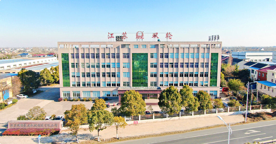
Jiangsu Double-wheel Pump Machinery Manufacting Co.,Ltd.
Jiangsu Double Wheel Pump Machinery Manufacturing Co., Ltd. is China Large Flow Rate Rain Water Pump Manufacturers and Wholesale Large Flow Rate Rain Water Pump Factory. The company is located in the scenic Yangtze River bank, Jiangyin Bridge, Beijing-Shanghai Expressway, Shanghai-Nanjing Expressway, Ningtong Expressway, Ningjingyan expressway running through the north and south, the traffic is very convenient, the geographical position is esteemed good. It is a production base specializing in non-sealed self-priming pumps, rain pumps, long-axis liquid pumps, chemical centrifugal pumps, positive displacement pumps and environmental protection equipment and mechanical equipment. The company has two production bases, covering an area of nearly 60,000 square meters, of which the eastern base covers an area of 33,000 square meters, the western base covers an area of 27,000 square meters, six modern production workshops, two installation workshops, a professional test workshop, a variety of mechanical processing equipment more than 160 sets, including a pump comprehensive performance test platform, Can test diameter 32-1200mm, motor power 1.1-1200KW, voltage 380V-10KV of various types of pumps, scientific research, development, manufacturing, processing, promotion, application of its own system. In the past two years, the company has closely followed the national industrial policy, made a big deal about environmental protection, and undertaken a large number of sewage treatment projects, which is unique in the environmental protection industry.
Certificate Of Honor


-
0

Be established in
-
0+

Professional personnel
-
0 million

Registered capital
-
0 ㎡

Plant area
After-Sales Service
Maintenance and Technical Support
Comprehensive lifecycle support for large flow rainwater pump stations — from hydraulic design consultation and commissioning through annual maintenance programs, 24/7 emergency response, and long-term infrastructure upgrade planning across the 25+ year operational life of your pump station.
Maintenance and Spare Parts
Keeping your flood defense infrastructure ready when it matters most
- Pre-Storm Season Inspection Service: We offer an annual pre-storm season inspection contract covering all RWP units in a pump station. The inspection includes: motor winding insulation resistance test, bearing vibration and temperature check, shaft seal condition assessment, impeller visual inspection via access port, non-return valve operation test, control panel function test, level sensor calibration verification, and telemetry system check. A written inspection report with maintenance recommendations is provided after each visit, giving water authorities confidence that their infrastructure is storm-ready before each season.
- On-Site Strategic Spare Parts Stock: For critical flood control pump stations, we prepare a station-specific spare parts list categorized by criticality: immediate (on-site): one complete set of shaft seals for all units, one set of impeller wear rings, one spare level sensor, and one spare VFD drive unit (matched to the installed motor rating). Near-term (available within 48 hours from our warehouse): one replacement impeller per duty configuration, one set of main bearings per unit type, one replacement motor for the most common rating in the station. This tiered strategy ensures rapid response to any component failure without requiring replacement of the entire pump unit.
- Impeller Replacement and Rebalancing: After extended service handling grit-laden storm runoff, impellers may develop erosion-induced imbalance that increases vibration levels. We offer a factory impeller refurbishment service — the impeller is returned to our factory, inspected, rebuilt or replaced if beyond repair, dynamically rebalanced to ISO 1940 G6.3 (the appropriate grade for large low-speed storm pump impellers), and returned with a new balance certificate. This service can extend impeller service life significantly compared to outright replacement.
- Control System Firmware and Software Support: The RWP control panel PLC firmware and HMI software are maintained and updated by our controls engineering team. Updates may include improvements to level control algorithms, enhanced diagnostic features, cybersecurity patches for SCADA interface modules, and protocol updates for GSM/4G telemetry modules as cellular network technology evolves. Contracted customers receive firmware updates automatically with installation instructions and telephone support.
- 25-Year Spare Parts Availability Commitment: Rainwater pump stations are designed for 25+ year service lives. We commit to maintaining spare parts availability for all critical components (impellers, casings, shaft assemblies, bearings, seal assemblies, control components) for a minimum of 15 years from original delivery. Beyond 15 years, we provide advance notice of component obsolescence with recommended replacement options — including upgrades that improve performance or energy efficiency relative to the original specification.
Professional Technical Support
Hydraulic engineering expertise across the full project and operational lifecycle
- Catchment Hydrology and Pump Sizing Assistance: At the project design stage, our hydraulic engineering team assists with design storm flow rate calculation, pump configuration selection, and number-of-pumps determination. We use industry-standard hydrological methods (Rational Method, time-area, storage routing) appropriate to the catchment size and data availability. Our sizing recommendation comes with a written hydraulic design memorandum suitable for inclusion in your project design report and regulatory submission.
- Wet Well Design Review per ANSI/HI 9.8: Wet well geometry is reviewed against ANSI/HI 9.8 Pump Intake Design guidelines before manufacturing commences. We issue a written confirmation of ANSI/HI 9.8 compliance or a list of recommended geometric modifications to the civil design to prevent inlet vortexing, turbulence, and air entrainment at the pump inlet. For large and critical installations, physical scale model testing of the wet well can be arranged at specialized hydraulic laboratories.
- Commissioning and First-Start Supervision: Factory-trained commissioning engineers attend site for pump station first start, verifying correct mechanical installation (pump alignment, coupling condition, bearing housing condition), control system set point calibration (start levels, stop levels, lag pump start levels, high-water alarm levels), VFD parameter setting, telemetry commissioning, and performance verification. A commissioning report confirming that each pump unit meets its specified performance is provided for the project handover documentation.
- 24/7 Emergency Flood Response Support: During major storm events, water authority operators require immediate technical support when a pump fault alarm is received. Our emergency technical support line is staffed 24 hours a day during storm alert periods. We respond within one hour to any critical pump fault report with remote diagnostic guidance — reviewing telemetry data, identifying probable fault cause, and guiding local operators through safe restart procedures or temporary remedial measures. Where physical attendance is required, we coordinate emergency site attendance within 24 hours for contracted accounts.
- Pump Station Capacity Upgrade Engineering: As urban development increases catchment imperviousness and climate change intensifies design storms, pump stations originally sized for a 1-in-20-year event may need to be upgraded to handle 1-in-50 or 1-in-100-year events. Our engineering team performs a capacity audit of existing installations — assessing whether additional pump units can be added within the existing wet well structure, whether larger impellers can be fitted to existing motor drives, or whether a new parallel pump station is required — providing water authorities with a cost-ranked set of upgrade options before major capital investment decisions are made.

+86-0523- 84351 090 /+86-180 0142 8659


Welcome To
Jiangsu Double-Wheel Pump
Add 1: Hongguang Industrial Park, Jingjiang City, Jiangsu Province, China
Add 2: No.68, Xinyi Road, Industrial Park, Jingjiang City, Jiangsu Province, China
Contact
-
Tel:
+86-0523- 84351 090
+86-180 0142 8659 -
FAX:
+0523-8435 5588
- E-mail: